


Plantation Drive at Micro Coils


Plantation Drive at Micro Coils Read More »
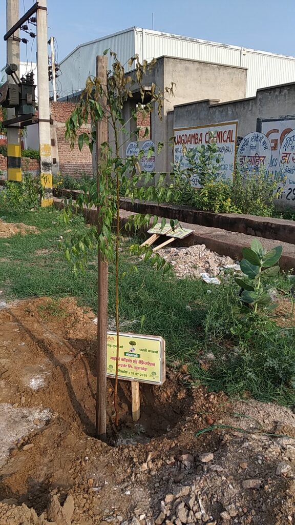
Micro Coils organized a meaningful and impactful plantation drive as part of its ongoing commitment to environmental sustainability and community responsibility. The initiative brought together employees from across departments, all united by a shared purpose—to contribute towards a greener and healthier future.
The drive saw enthusiastic participation, with employees actively planting saplings within and around the premises. The activity not only helped enhance the green cover but also created a sense of ownership and responsibility towards the environment. Each sapling planted symbolized a step forward in reducing carbon footprint and promoting ecological balance.
The event was carefully planned, with designated areas prepared for planting and guidance provided on proper techniques to ensure the healthy growth of the saplings. Participants were encouraged to understand the importance of nurturing these plants over time, reinforcing the idea that sustainability is a continuous effort rather than a one-time activity.
Beyond its environmental impact, the plantation drive also served as a team-building exercise. It fostered collaboration, encouraged meaningful engagement outside of routine work, and strengthened the bond among employees. The hands-on experience of planting trees created a lasting impression, reminding everyone of their role in protecting the planet.
Through this initiative, Micro Coils reaffirmed its dedication to sustainable practices and responsible growth. The plantation drive was not just an activity, but a reflection of the company’s vision to create a positive impact beyond business.
As the saplings grow, they will stand as a living testament to Micro Coils’ commitment to a greener tomorrow—one that values nature, nurtures responsibility, and inspires collective action for the environment.
Plantation Drive at Micro Coils Read More »


Micro Coils marked Women’s Day with a heartfelt and inspiring celebration that honored the strength, resilience, and achievements of the women within the organization. The event brought together employees across teams to recognize the invaluable contributions women make not only in the workplace but also in shaping a progressive and inclusive culture.
The ceremony began with a warm welcome, followed by leadership addresses that emphasized the importance of gender equality, respect, and opportunity. Thought-provoking discussions and engaging activities highlighted the journeys of women professionals, encouraging open conversations around growth, challenges, and empowerment. The celebration created a space where voices were heard, experiences were shared, and inspiration flowed freely.


One of the key highlights of the event was the recognition of women employees for their dedication, performance, and impact within the company. Their stories served as a powerful reminder of perseverance and excellence. Interactive sessions and team activities added energy to the celebration, strengthening bonds and fostering a sense of unity among colleagues.
The venue was thoughtfully decorated to reflect the spirit of the occasion, creating a vibrant and uplifting atmosphere. The event concluded with a token of appreciation for all women employees, symbolizing gratitude and respect for their contributions.
Through this Women’s Day celebration, Micro Coils reinforced its commitment to building an inclusive workplace where everyone has the opportunity to thrive. The event was not just a celebration, but a reflection of the organization’s values—recognition, respect, and empowerment.
As the celebration came to a close, it left behind a sense of pride, motivation, and renewed commitment to continue fostering an environment where women are supported, celebrated, and empowered every day
Women’s Day at Micro Coils Read More »

The New Year 2026 began on a spiritually uplifting note at Micro Coils, as the organization hosted a serene and devotional Sundarkand Paath Ceremony. The event brought together employees, leadership, and their families in an atmosphere filled with faith, positivity, and collective prayer, setting a meaningful tone for the year ahead.
The recitation of Sundarkand Paath, a sacred chapter from the Ramayana symbolizing strength, devotion, and the triumph of good over evil, created a deeply calming and energizing environment. The rhythmic chanting of verses resonated across the venue, fostering a sense of unity and inner peace among all attendees. The ceremony was not just a religious gathering, but a reflection of the company’s values—resilience, teamwork, and a shared vision for growth.
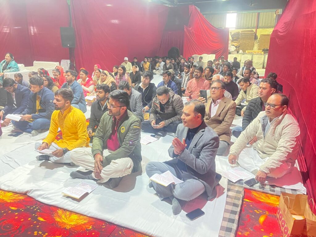
The event was thoughtfully organized, with a beautifully decorated space that enhanced the spiritual ambiance. Participants actively engaged in the paath, followed by an aarti that further elevated the collective energy. The ceremony concluded with the distribution of prasad, symbolizing blessings and goodwill for everyone present.
Such initiatives highlight Micro Coils’ commitment to nurturing not just professional excellence but also emotional and spiritual well-being within the organization. By beginning the year with gratitude and positivity, the company reinforced its culture of togetherness and mindfulness.

The Sundarkand Paath Ceremony served as a reminder that success is not only measured in business achievements, but also in the strength of community and shared values. As Micro Coils steps into 2026, the event leaves behind a sense of optimism, renewed energy, and a collective aspiration for a prosperous and harmonious year ahead.


Micro Coils India has been honored as the “Manufacturer of the Year” at the National Business Excellence Awards 2026, presented by the MSME Chamber of Commerce and Industry of India.
This prestigious recognition, received by our Managing Director, Mr. Anurag Gupta, reflects our unwavering commitment to innovation, quality, and engineering excellence. It is a testament to the trust our clients place in us and the relentless dedication of our team.
At Micro Coils, we continuously strive to push boundaries, deliver high-performance solutions, and contribute meaningfully to the growth of the industry. Achievements like these motivate us to raise the bar even higher.
We extend our sincere gratitude to the organizers and everyone who has been a part of this journey. This recognition belongs to every member of the Micro Coils family.
Here’s to continued innovation and many more milestones ahead.
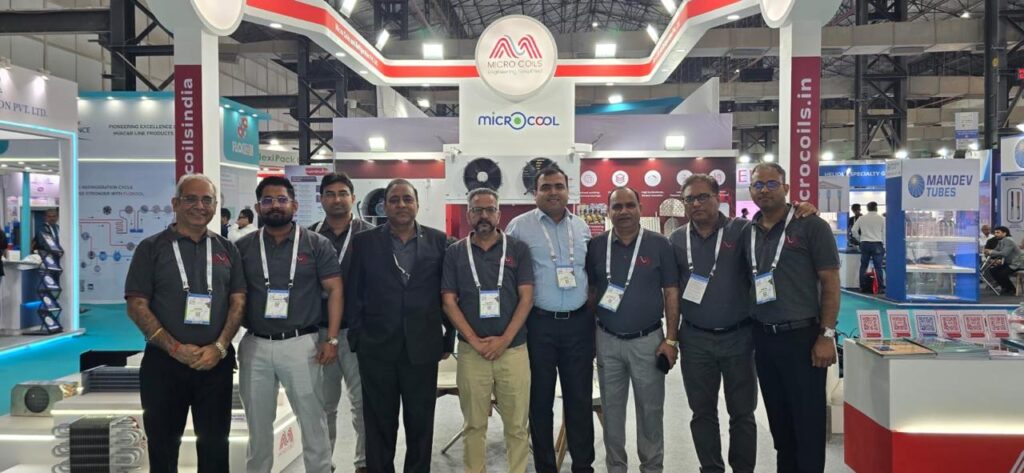

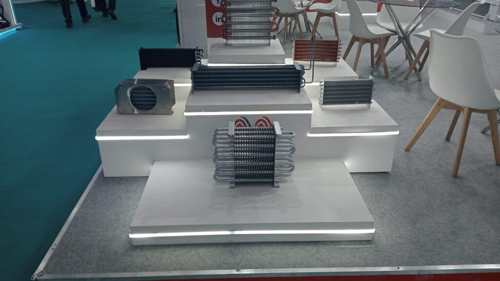
Microcoils recently participated in ACREX India 2026, South Asia’s largest and most influential exhibition for HVAC, refrigeration, and building automation. Held in Mumbai, the event served as a dynamic platform for global industry leaders, innovators, and technology experts to come together, showcase cutting-edge solutions, and drive meaningful discussions around sustainability, energy efficiency, and the future of smart infrastructure.
At the event, Microcoils showcased its advanced capabilities and engineering excellence, presenting innovative solutions tailored to evolving industry demands. The exhibition provided an ideal opportunity to engage with industry professionals, partners, and potential clients, enabling insightful conversations and knowledge exchange.
Participation in ACREX India 2026 not only helped strengthen existing relationships but also opened doors to new collaborations and business opportunities. It further reinforced Microcoils’ commitment to delivering high-performance, reliable, and future-ready solutions, while actively contributing to the growth and transformation of the HVAC ecosystem.
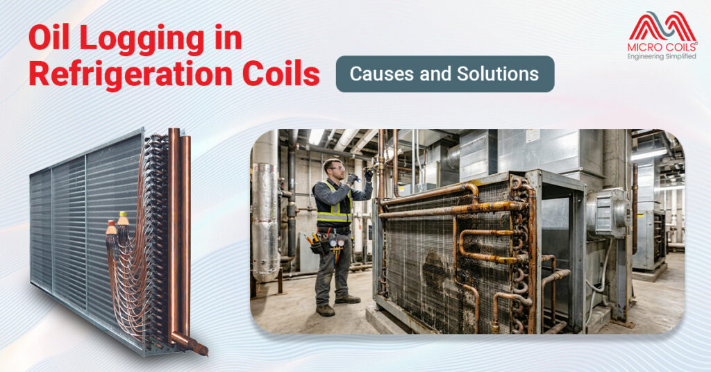
Oil logging represents one of the most insidious performance degradation issues facing commercial and industrial refrigeration systems today. Unlike catastrophic failures that announce themselves with alarms and shutdowns, oil logging creeps in gradually, quietly eroding system efficiency while driving up operational costs. Facility managers and refrigeration technicians often misdiagnose the symptoms, attributing reduced cooling capacity to refrigerant charge issues or compressor problems when the real culprit sits trapped within the refrigeration coil itself. Understanding oil logging—its causes, consequences, and solutions—separates reactive maintenance programs from proactive asset management strategies that protect both equipment investments and bottom-line performance.
Oil logging occurs when lubricating oil from the compressor accumulates in the evaporator coil rather than returning to the compressor crankcase where it belongs. In a properly functioning refrigeration system, a small amount of oil circulates with the refrigerant throughout the entire circuit, lubricating moving parts and providing critical protection to the compressor. This oil should continuously return to the compressor, maintaining proper lubrication levels and preventing oil starvation. When oil becomes trapped in the coil instead, it creates a cascading series of problems that compromise system performance and accelerate equipment wear.
The impact of oil logging extends far beyond simple efficiency loss. A coil filled with excessive oil reduces the effective heat transfer surface area, forcing the compressor to work harder and longer to achieve the same cooling effect. Energy consumption increases by 15-30% in moderately oil-logged systems, with severe cases showing even higher penalties. Perhaps most critically, the compressor itself faces lubrication starvation as its oil supply diminishes, creating conditions for premature bearing failure and catastrophic compressor damage that can cost tens of thousands of dollars to repair or replace.
Refrigeration oil doesn’t pump itself through the system—it rides along with refrigerant vapor as an entrained mist. The velocity of refrigerant vapor moving through piping and coils determines whether oil successfully travels through the circuit or settles in low points and horizontal runs. In vertical risers, refrigerant velocity must exceed minimum thresholds (typically 700-1000 feet per minute depending on pipe diameter) to carry oil upward against gravity. When velocity drops below these critical levels, oil falls back down and accumulates in the lowest points of the system, which often means the evaporator coil.
The relationship between system load, refrigerant velocity, and oil return creates a delicate balance that designers must carefully consider. At full load conditions, refrigerant mass flow rates are high, velocities are adequate, and oil circulates properly throughout the system. During partial load operation—which represents the majority of operating hours for most systems—refrigerant flow decreases, velocities drop, and oil migration slows or reverses. This is why properly designed systems incorporate oil return strategies that function across the full range of operating conditions, not just at peak capacity.
Inadequate refrigerant velocity in the evaporator coil stands as the single most common design-related cause of oil logging in commercial refrigeration systems. Engineers who undersize liquid lines or design coil circuits without considering minimum velocity requirements create systems predisposed to oil accumulation from day one. Horizontal runs of refrigeration piping without proper pitch (minimum 0.5 inches per 10 feet of run) allow oil to pool in low spots rather than draining back toward the compressor. Oversized evaporator coils, while seemingly beneficial for heat transfer, can actually work against oil return by reducing refrigerant velocity below critical thresholds during normal operation.
Circuit design within the coil itself plays an equally crucial role in determining oil return characteristics. Multi-circuit coils with unequal refrigerant distribution create conditions where some circuits experience adequate velocity while others become oil traps. Long horizontal headers that feed multiple coil circuits often accumulate oil because refrigerant velocity in headers is inherently lower than in individual circuits. Coils designed without consideration for oil return—prioritizing only heat transfer performance—inevitably experience oil logging issues in real-world applications. The most problematic designs combine long horizontal circuits, multiple elevation changes, and inadequate refrigerant velocities into a perfect storm of oil retention.
Low load operation transforms even well-designed systems into potential oil logging scenarios over extended periods. When ambient temperatures drop, cooling loads decrease, and compressors cycle or run at reduced capacity through variable-speed control, refrigerant mass flow rates plummet. The AC cooling coil that performed flawlessly during peak summer conditions may become an oil trap during mild spring weather when the system operates at 30-40% of design capacity. Prolonged low-load operation allows oil to gradually accumulate in coils, creating problems that won’t manifest until the system is called upon to deliver full capacity again.
Refrigerant charge issues—both undercharge and overcharge conditions—significantly impact oil logging tendencies in refrigeration systems. Undercharged systems run higher superheat, reducing refrigerant density and velocity in the suction line and evaporator, which impairs oil entrainment and return. Overcharged systems flood back liquid refrigerant to the compressor, washing oil out of the crankcase and sending excessive amounts into the refrigeration circuit. Improper oil charge in the compressor crankcase itself creates similar issues: too little oil and the compressor starves; too much oil and the excess circulates through the system, overwhelming the coil’s ability to return it. Each of these charge-related issues compounds oil logging risk while simultaneously making diagnosis more difficult.
Declining system capacity represents the earliest and most common symptom of oil logging, though it’s often attributed to other causes initially. A refrigeration coil with significant oil accumulation simply cannot transfer heat as effectively as a clean coil, forcing longer run times to achieve setpoint temperatures. Facility managers notice food cases taking longer to pull down after restocking, walk-in coolers that struggle to recover after door openings, or process cooling applications that can’t maintain temperature tolerances. These capacity losses typically develop gradually over weeks or months, making them easy to overlook or rationalize until the degradation becomes severe enough to impact operations.
Abnormal temperature and pressure readings provide concrete diagnostic evidence when compared against baseline system performance data. Suction pressure drops lower than normal for the given load conditions because the oil-logged evaporator cannot evaporate refrigerant efficiently. Superheat readings climb higher than design specifications as the effective evaporator surface area shrinks due to oil coating internal surfaces. Compressor discharge temperatures increase as the machine works harder and longer to overcome the reduced system capacity. The compressor crankcase oil level visibly drops below the sight glass minimum as oil migrates out of the compressor and into the refrigeration circuit, providing the most definitive visual confirmation of oil logging.
Oil return procedures provide the fastest route to restoring system performance when oil logging is identified and confirmed. The most straightforward approach involves temporarily raising the evaporator temperature and increasing refrigerant velocity to mobilize trapped oil and push it back toward the compressor. This can be accomplished by reducing cooling load, adjusting expansion valve settings to run lower superheat, or in extreme cases, briefly shutting down the system and allowing the evaporator coil to warm above refrigerant saturation temperature. Once oil begins moving, the system should be run at higher loads to maintain velocity until the compressor crankcase refills to proper levels.
Hot gas defrost cycles, where applicable, offer an effective oil clearing mechanism for systems already equipped with this functionality. Introducing hot discharge gas directly into the evaporator rapidly raises coil temperature and refrigerant velocity, creating ideal conditions for flushing trapped oil back through the suction line. This approach works particularly well in low-temperature applications where oil logging is most problematic due to higher oil viscosity at cold temperatures. However, hot gas defrost must be carefully controlled to avoid liquid slugging the compressor or creating pressure spikes that damage system components. Multiple short defrost cycles often prove more effective than single extended cycles for oil return purposes.
Establishing baseline performance data for each refrigeration system creates the foundation for early oil logging detection through trend analysis. Monthly recording of key parameters—suction and discharge pressures, superheat and subcooling values, compressor runtime hours, and crankcase oil level—provides the comparative data necessary to identify gradual performance degradation. When plotted over time, these metrics reveal patterns that distinguish oil logging from refrigerant charge issues, fouled coils, or failing compressors. This data-driven approach replaces reactive troubleshooting with predictive maintenance that addresses oil logging before it impacts operations or damages equipment.
Regular oil level monitoring and oil quality testing deserve priority status in comprehensive refrigeration maintenance programs. Visual inspection of compressor crankcase oil levels through sight glasses should occur during every routine service visit, with any deviations from normal levels triggering investigation. Annual oil sampling and laboratory analysis reveals contamination, acid formation, and viscosity breakdown that indicates system problems requiring attention. When oil levels consistently run low despite no external leaks, oil logging becomes the prime suspect requiring systematic evaluation of system design and operating conditions. The relatively minor cost of routine oil testing pales compared to compressor replacement expenses or lost product due to refrigeration system failures.
Oil logging in refrigeration coils represents a preventable performance degradation that costs the industry hundreds of millions of dollars annually in wasted energy and premature equipment failure. The technical causes are well understood, diagnostic methods are readily available, and effective solutions exist for both new construction and existing system remediation. Yet oil logging persists because many organizations treat refrigeration as a commodity infrastructure rather than a sophisticated system requiring expert design, proper commissioning, and proactive maintenance. The gap between best practices and common practice creates ongoing operational penalties and unnecessary capital expenditure replacing equipment that should have delivered decades of reliable service.
Absolutely. New systems can experience oil logging within days if improperly commissioned. Common installation errors include incorrect refrigerant charge, failure to achieve proper evacuation leaving moisture in the system, wrong oil type for the specified refrigerant, or contractor shortcuts during pressure testing that introduce contaminants. Always verify proper startup procedures were followed and document baseline performance metrics immediately after commissioning to establish reference points for future comparisons.
No, synthetic oils don’t eliminate oil logging—they simply change its characteristics. POE (polyolester) and PVE (polyvinylether) synthetic oils offer better miscibility with HFC refrigerants at low temperatures compared to mineral oils, potentially reducing accumulation severity. However, synthetics are hygroscopic, absorbing moisture more readily, which creates acid formation risks. They also cost significantly more than mineral oils. Oil type selection must match refrigerant choice and application requirements, but proper system design remains essential regardless of oil chemistry.
Stainless steel systems are more corrosion-resistant but can suffer from stress corrosion cracking in chloride environments – watch for hairline cracks near welds. Exotic materials like titanium or Hastelloy are highly resistant to chemical attack but may show different thermal expansion behaviors. Adjust your baseline parameters accordingly. The key is understanding your specific material’s vulnerabilities and focusing inspection efforts there. Document material specifications when purchasing from pillow plate manufacturers so your maintenance team knows exactly what they’re working with.
Monthly visual inspections of compressor oil levels provide minimum monitoring frequency, with quarterly detailed performance assessments recommended for critical systems. High-risk applications—low-temperature freezers, systems with long refrigerant line runs, or those operating under highly variable loads—warrant monthly performance testing including pressure-temperature analysis and superheat verification. Seasonal checks before peak cooling season ensure systems perform when needed most. Document all readings to establish trends rather than relying on single-point measurements that miss gradual degradation patterns.
This approach addresses symptoms temporarily while worsening the underlying problem. Adding oil without removing trapped oil from coils increases total system oil charge, meaning even more oil circulates through refrigerant circuits and accumulates in evaporators. The compressor may show proper oil levels briefly, but logging accelerates as excess oil overwhelms the system’s oil return capability. Correct solution requires identifying why oil isn’t returning, implementing proper oil recovery procedures, then charging only the manufacturer-specified oil quantity after trapped oil returns.
Refrigeration industry consensus strongly discourages aftermarket oil additives in commercial systems. These products may temporarily improve oil flow characteristics but often void equipment warranties and create unforeseen chemical reactions with refrigerants, metals, or elastomers in the system. Some additives break down under refrigeration operating conditions, producing contaminants that damage compressors or clog expansion devices. Instead, address root causes through proper system design, correct oil selection for your specific refrigerant, and maintenance practices proven effective across millions of operating hours.
Oil Logging in Refrigeration Coils: Causes and Solutions Read More »
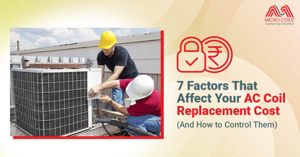
Wildly varying quotes between contractors can make evaporator coil replacement feel overwhelming. What drives these differences? Understanding the factors puts you in control, helping you make informed decisions rather than simply accepting whatever number appears on an estimate.
The cost to change AC coil components depends on multiple variables. Some you can’t control; others you can influence significantly. Smart property managers and facility operators who understand these factors negotiate better deals, avoid unnecessary expenses, and make decisions serving their long-term interests.
Tonnage directly impacts replacement expenses. Larger coils use more material, weigh more, require additional labor to handle, and often need specialized equipment for installation. A 3-ton residential unit needs a smaller, simpler coil than a 50-ton commercial rooftop unit.
Commercial systems present additional complexity—buildings with multiple air handlers might need several coils replaced, each potentially different in size and configuration. Equipment in office buildings, retail centers, and industrial facilities often ranges from 5 tons to over 100 tons per unit.
Many existing systems were initially oversized by contractors who believed bigger is always better. Replacing an oversized coil with a properly sized unit can reduce both immediate replacement expense and long-term operating costs.
How to control this factor: Request a proper load calculation before replacement. Manual J calculations for residential buildings or equivalent commercial load analysis determines your actual cooling needs. Building improvements—new insulation, efficient windows, LED lighting generating less heat—may have reduced your actual cooling load since the original installation. You might discover your existing 5-ton system only needs a 4-ton replacement, saving substantially.
AC Evaporator coil units come in multiple configurations, affecting both performance and expense. A-coils form an “A” shape, fitting well in vertical air handlers with limited width. N-coils create an “N” pattern, offering more surface area in the same footprint. Slab coils sit in a single flat plane, typically used in horizontal applications. Each design carries different manufacturing complexity affecting final expense.
Cased coils include their own metal housing with mounting flanges, simplifying installation but adding material expense. Uncased coils integrate directly into air handler cabinets, reducing material expense but requiring precise field fabrication.
Standard copper tubing with aluminum fins offers excellent heat transfer characteristics. All-aluminum construction reduces expense but provides lower heat transfer efficiency. The choice depends on your specific operating environment and performance requirements.
Coil coatings add expense but extend service life dramatically in corrosive environments. Coastal facilities, industrial plants with chemical exposure, or buildings in areas with high atmospheric pollution benefit from protective coatings:
Standard uncoated coils work fine in benign environments. Modern office buildings with good filtration in moderate climates don’t need expensive protective coatings—specifying them wastes money without delivering value.
How to control this factor: Match coil specifications to your actual operating environment rather than buying maximum protection for every application. Request itemized quotes showing base coil expense separate from coating options. This transparency reveals exactly what you’re paying for protective treatments.
Consider all-aluminum coils for applications where copper’s superior heat transfer isn’t critical. Light commercial applications, backup systems, or facilities in mild climates may operate perfectly well with aluminum coils at reduced expense.
Your system’s refrigerant significantly affects replacement planning. R-22 (Freon) systems present the most challenging scenario—production ceased in 2020, making this refrigerant increasingly scarce. If your existing system runs R-22, you face a critical decision: replace the coil with another R-22 unit or upgrade the entire system to modern refrigerant.
Replacing an R-22 coil with another R-22 unit makes sense only if the rest of your system remains in excellent condition with years of service life remaining. Limited availability may inflate pricing beyond reasonable levels. Even then, securing R-22 coils becomes increasingly difficult as manufacturers discontinue production.
R-410A represents current standard refrigerant for most residential and light commercial applications. Systems designed for this refrigerant operate at higher pressures than R-22, requiring coils specifically rated for these conditions. You cannot install an R-410A coil in an R-22 system or vice versa without complete system replacement.
Newer refrigerants like R-32 and R-454B are entering the market as the industry transitions toward lower global warming potential options. Early adoption carries premium pricing as these products represent newer technology with limited production volumes.
How to control this factor: If replacing a coil in an R-22 system, seriously evaluate complete system replacement instead. Calculate total expense over the next 5-10 years, including increasingly expensive R-22 refrigerant for repairs and recharging. Often, full system replacement to R-410A proves more economical long-term despite the higher immediate expense.
For R-410A systems, verify that replacement coils come from reputable heat exchanger manufacturer sources with proper certification. Avoid generic imported coils lacking AHRI certification, as these may fail prematurely despite lower initial expense.
Where your coil sits and how easily technicians can access it dramatically affects labor requirements. Two identical coils might carry vastly different total replacement expenses based purely on installation difficulty.
Coils in basement air handlers with clear working space represent straightforward replacements. Coils in cramped attic installations accessed through small openings demand significantly more time and effort. Attic installations present multiple challenges:
Commercial rooftop units require roof access, often needing cranes, rigging equipment, or specialized lifting gear to remove old coils and install replacements. Large coils weighing several hundred pounds cannot be manually carried up ladders. Equipment rental, certified operators, and additional safety measures all add expense.
Building access restrictions affect commercial installations significantly. Some facilities require contractors to work after hours or weekends to avoid disrupting operations—premium rates for off-hours work increase labor expenses substantially.
How to control this factor: Schedule replacements during optimal conditions rather than emergency situations. Planned replacement allows contractors to bid competitively rather than charging emergency premiums. You can schedule work during normal business hours at standard labor rates.
Request detailed explanation of access plans before accepting quotes. Understanding how contractors plan to physically accomplish installation reveals potential problems and allows you to address access issues proactively.
Consider providing building access assistance. If you have maintenance staff or building engineers familiar with the facility, coordinate with contractors to streamline access to mechanical rooms, rooftops, or crawlspaces—reducing contractor time reduces billable hours.
Evaporator coils don’t operate in isolation—they function as integrated components within complete systems. Proper matching with other components affects both immediate replacement expense and long-term system performance.
The evaporator coil must match your outdoor condensing unit’s capacity and refrigerant flow characteristics. Mismatched components reduce efficiency, shorten equipment life, and may void manufacturer warranties. Proper matching requires attention to:
Capacity matching—the evaporator and condenser must handle identical cooling capacities. Installing a 3-ton evaporator with a 4-ton condenser creates imbalance causing poor performance and potential compressor damage.
SEER rating compatibility matters too. Modern high-efficiency condensing units require matching high-efficiency evaporator coils to achieve rated performance. Installing a standard efficiency evaporator with a high-efficiency condenser wastes the condenser’s potential while failing to deliver promised energy savings.
The expansion valve or orifice controlling refrigerant flow into the evaporator must match the new coil’s characteristics. Many coil replacements require new expansion devices adding parts and labor expenses.
Evaporator coils require specific airflow volumes for proper operation. Older blower motors or ductwork restrictions that barely worked with the original coil may prove inadequate for a new coil with different pressure drop characteristics—upgrading blowers or modifying ductwork adds expense beyond the coil itself.
How to control this factor: Request documentation proving the proposed replacement coil matches your existing outdoor unit according to manufacturer specifications. AHRI (Air Conditioning, Heating, and Refrigeration Institute) publishes certified combinations showing which indoor and outdoor units work together properly.
Verify AHRI certification numbers for your specific combination. Contractors sometimes recommend “close enough” pairings that aren’t factory certified—these combinations may work adequately but won’t deliver rated performance and typically void manufacturer warranties.
Resist pressure to upgrade beyond your actual needs. If your existing system uses standard efficiency components, replacing only the failed coil with an equivalent standard efficiency unit makes economic sense unless you’re simultaneously upgrading the entire system.
Geographic location, contractor business model, and local market conditions create significant variation in the labor portion of your total expense.
Metropolitan areas with high costs of living and strong construction markets command premium labor rates. Rural areas with lower costs and less competition typically offer lower rates.
Contractor business models affect pricing substantially. National franchise operations carry higher overhead—franchise fees, national advertising contributions, corporate management layers—that must be recovered through higher pricing. They offer brand recognition, standardized processes, and often more extensive warranties.
Regional contractors with multiple locations balance moderate overhead with established reputations and service capacity, typically pricing between national chains and small local operators.
Small local contractors operate with minimal overhead, often owner-operated with one or two technicians. They frequently offer the lowest pricing but may lack capacity for large projects or extended warranty support.
Specialization influences efficiency and pricing. Companies specializing in commercial HVAC typically handle commercial coil replacement more efficiently than residential-focused contractors occasionally working commercial projects—and vice versa for residential work.
Seasonal demand fluctuates dramatically in HVAC. Peak cooling season sees elevated pricing as contractors operate at capacity with full schedules. Off-season winter months often bring discounted pricing as contractors seek work to keep technicians employed.
How to control this factor: Obtain multiple competitive quotes—at least three, ideally five for significant commercial projects. Competitive bidding reveals market rates and identifies outliers pricing far above or below reasonable ranges.
Schedule replacements during shoulder seasons (spring and fall) when demand moderates. Contractors often discount work during slower periods to maintain steady workflow.
Separate emergency service from planned replacement. Emergency calls command premium pricing—nights, weekends, holidays, or immediate response during heat waves all carry surcharges. Planning replacement before complete failure allows standard-rate scheduling.
Regulatory requirements add expenses many property owners don’t anticipate. Understanding what’s legally required versus what contractors suggest protects against both overcharges and code violations.
Permit requirements vary by jurisdiction but typically apply to coil replacement in most areas. Permits ensure work meets safety and building codes while providing documentation of proper installation.
Some contractors operate without pulling permits, offering lower quotes by skipping this regulatory requirement. This creates several problems—code violations discoverable during future property sales, lack of inspection verification, potential insurance claim denials, and liability if improperly installed equipment causes damage.
Municipal permit applications and fees:
Electrical code compliance modifications:
Refrigerant handling and environmental compliance:
Energy code compliance for replacement equipment:
How to control this factor: Verify permit requirements with your local building department directly rather than relying solely on contractor representations. Understanding actual requirements prevents both overcharges for unnecessary permits and violations from skipped required permits.
Include permit responsibility in contract specifications—clarify whether the contractor obtains and pays for permits (typical) or if you’ll handle this separately. Ensure permits appear as line items in quotes rather than buried in vague “installation” charges.
Request copies of all permits and final inspection approvals. These documents prove work was performed legally and may be required for property sales, insurance claims, or future service work.
Don’t pay premium prices for “code upgrades” without verification. Contractors sometimes suggest extensive modifications claiming code requirements when alternatives meeting code exist at lower expense.
The cost to change an AC coil component reflects multiple factors, but you’re not helpless. Understanding what drives pricing reveals where you can influence outcomes and where you simply need to accept market realities.
System size, refrigerant type, and accessibility represent largely fixed factors—you can’t change your building’s layout or your equipment’s refrigerant. Strategic decisions about timing, material selection, contractor choice, and specification details, however, create meaningful opportunities to control expenses without sacrificing quality.
Obtain multiple competitive quotes. Verify actual requirements rather than accepting contractor recommendations blindly. Schedule work strategically to avoid premium pricing periods. Match specifications to actual operating needs rather than over-specifying protective features your environment doesn’t require.
The lowest quote rarely delivers the best value. The goal isn’t minimizing immediate expense—it’s optimizing total cost of ownership over the equipment’s service life. Sometimes spending moderately more upfront for better materials, superior installation quality, or enhanced warranty coverage delivers better financial outcomes.
Approach coil replacement as a business decision requiring analysis rather than an emergency requiring immediate action. Even when facing failed equipment, taking time to understand options, verify requirements, and negotiate competitively serves your interests better than panicked acceptance of the first available quote.
Control what you can, understand what you can’t, and make informed decisions that serve your operational and financial objectives.
Simultaneous replacement makes sense primarily when both coils are similarly aged (10+ years) or when upgrading refrigerant types requires complete system conversion. Mismatched coil ages create warranty complications—new coils typically carry 10-year warranties while aging coils may fail soon after, requiring another service call and installation expense. However, if one coil remains relatively new (under 5 years) and compatible with the replacement, single-coil replacement proves more economical.
Technically possible, but most reputable contractors decline installation-only work due to liability concerns and warranty complications. When contractors supply equipment, they warranty both parts and labor. Installing customer-supplied equipment transfers all performance risk to the homeowner—if the coil fails or doesn’t perform properly, determining whether installation errors or defective equipment caused the problem becomes contentious. Additionally, you lose wholesale contractor pricing advantages and assume responsibility for verifying correct model selection and compatibility.
Stainless steel systems are more corrosion-resistant but can suffer from stress corrosion cracking in chloride environments – watch for hairline cracks near welds. Exotic materials like titanium or Hastelloy are highly resistant to chemical attack but may show different thermal expansion behaviors. Adjust your baseline parameters accordingly. The key is understanding your specific material’s vulnerabilities and focusing inspection efforts there. Document material specifications when purchasing from pillow plate manufacturers so your maintenance team knows exactly what they’re working with.
Contractor financing typically carries higher interest rates than personal loans or home equity lines of credit, sometimes reaching 18-24% APR after promotional periods end. Cash payments often qualify for 3-5% discounts. Credit card payments avoid financing charges if paid within billing cycles but may incur processing fees. Evaluate total financing costs over the entire repayment period—a moderately higher quoted price paid in cash may cost less overall than a lower quoted price with expensive financing terms.
Reputable contractors provide written change order procedures detailing how unexpected conditions get handled. Common surprises include corroded refrigerant lines requiring replacement, electrical deficiencies needing correction, or structural damage around the air handler. Require contractors to stop work, document the issue photographically, explain necessary repairs with itemized pricing, and obtain your written approval before proceeding. Never authorize vague “do whatever’s necessary” instructions—this creates billing disputes over whether additional work was truly required.
7 Factors That Affect Your AC Coil Replacement Cost (And How to Control Them) Read More »
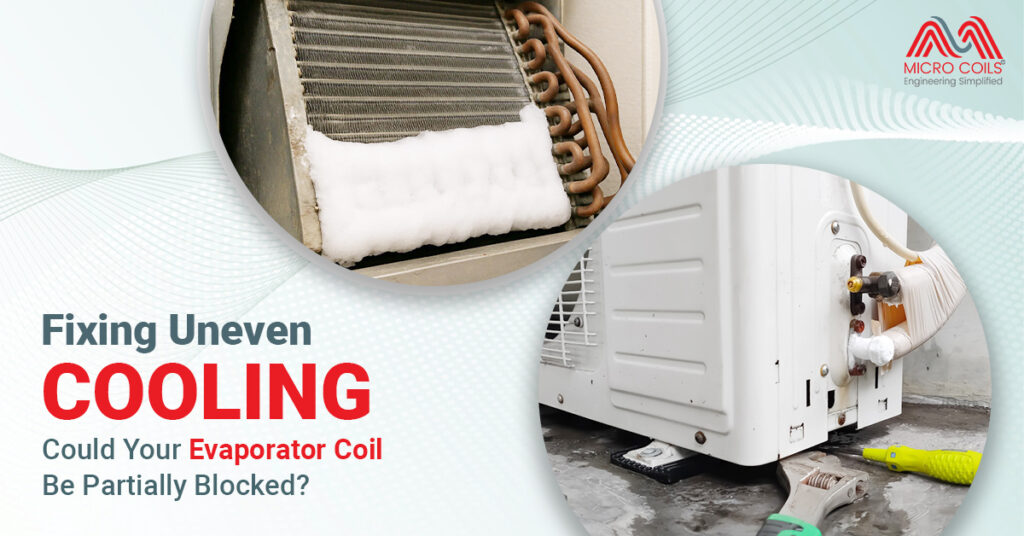
Temperature differences across your commercial facility create more than comfort complaints. When some zones stay cool while others overheat, you’re facing operational problems that cost money every day. The cause often sits inside your air handler a partially blocked evaporator coil that’s choking your cooling system.
For facility managers and building operators, understanding how blockages happen, spotting the warning signs, and knowing when to clean or replace saves thousands in energy costs and prevents expensive emergency repairs.
Your cooling system has two main parts that exchange heat. The AC condenser coil sits outside in the condensing unit on the roof or ground level. It releases heat from your building into the outdoor air. The AC evaporator coil unit sits inside your air handler and absorbs heat from the air circulating through your building.
Cold refrigerant flows through the evaporator coil. As warm return air from your building passes over this cold coil, heat transfers from the air to the refrigerant. The now-cooled air travels through your ductwork to different zones. The refrigerant, having absorbed heat, flows to the outdoor condenser where it releases that heat and cycles back.
When the entire coil surface works properly, all the air passing through gets cooled evenly. Blockages disrupt this process. Some sections of the coil can’t cool air effectively while other sections work overtime trying to compensate.
Commercial evaporator coils face tougher conditions than residential units. They run longer hours, handle more air volume, and encounter contaminants that home systems never see.
A completely blocked coil stops cooling entirely—you notice immediately. Partial blockages are sneaky. The system keeps running, but performance degrades in ways that create zone-to-zone temperature differences.
Air takes the path of least resistance. When part of your coil blocks up, air rushes through the clear sections and barely trickles through blocked areas. The air moving too fast through clear sections doesn’t have enough contact time to cool properly. Air crawling through blocked sections either gets overcooled or doesn’t cool at all.
Your AC cooling coil typically has multiple refrigerant circuits, usually 3 to 6 separate paths through the coil. Each circuit should handle equal amounts of refrigerant and cool equal amounts of air. Blockages throw this balance off. Circuits serving blocked coil sections can’t absorb heat properly. The refrigerant in those circuits stays too cold, possibly causing ice formation. Meanwhile, circuits in unblocked sections work harder, possibly overheating.
Temperature differences develop in the air leaving your coil. Instead of uniform 55°F air across the entire airflow, you get patches—some areas blowing 55°F, others pushing 62°F or warmer. This temperature-stratified air flows into your duct system. Branches near the cold patches deliver good cooling. Branches near warm patches can’t cool their zones adequately.
Static pressure increases throughout your duct system as the blockage reduces total airflow. Your blower motor works harder, uses more electricity, and still moves less air than it should.
Start by mapping the problem. Measure temperature in each zone during peak cooling hours using a reliable thermometer. Take readings at the same height—about 5 feet off the floor. Temperature differences exceeding 5°F between zones indicate distribution problems, likely from uneven coil performance.
Check supply air temperature at each air register. Normal supply air measures 55-60°F. If some registers blow 56°F while others push 64°F, your coil isn’t cooling uniformly. This points directly to blockage rather than duct problems, which typically show consistent supply temperatures but different air volumes.
Measure the temperature difference between return air and supply air. This “split” should run 18-22°F in most commercial comfort cooling. Splits below 15°F suggest inadequate cooling capacity from restricted airflow. Splits above 25°F might indicate severely reduced airflow from heavy blockage.
Review your building management system data if you have one. Look for:
Check static pressure directly by measuring pressure before and after the coil. Clean commercial coils typically show 0.3 to 0.8 inches of water column pressure drop. Readings above 1.0 inch indicate restriction. Increases of 30-50% above your baseline measurements warrant investigation.
Inspect the coil physically. Turn off power completely at the breaker and service disconnect. Remove access panels to view the coil. You’re looking for:
Also inspect for:
Commercial coil cleaning requires professional service in most cases. The methods used depend on blockage severity and coil accessibility.
When hiring contractors, verify:
Get written specifications covering:
Cleaning fixes surface blockages but can’t repair damage or restore lost capacity from deteriorated coils. Consider replacement when:
Taking Action
Partial blockages in your AC evaporator coil system cost money daily through wasted energy, accelerated equipment wear, and operational disruptions. Temperature differences between zones are your early warning signal.
Systematic diagnosis using temperature measurements and physical inspection identifies blockage severity. Professional cleaning restores performance in most cases, though severely deteriorated or repeatedly failing coils need replacement.
Preventive maintenance through upgraded filtration, scheduled inspections, proper drainage, and biological control keeps coils clean and systems running efficiently. The investment pays back through lower energy costs, extended equipment life, and reliable operation.
Address the problem now before a partially blocked coil becomes a completely failed system during your busiest season. Your cooling system is critical infrastructure—maintain it accordingly.
Professional cleaning duration varies by unit size and blockage severity. A standard 10-20 ton rooftop unit typically requires 2-4 hours including setup, cleaning, and rinsing. Larger air handlers serving 50+ tons may need 6-8 hours. Multiple-unit facilities should schedule cleaning across several days to maintain partial cooling capacity during service.
Yes, but monitor performance closely. Reduce cooling loads by adjusting setpoints upward 2-3 degrees and limiting occupancy in problem zones if possible. Check drain pans daily for overflow. If you notice ice formation on refrigerant lines, rapidly declining airflow, or unusual noises from the compressor, shut down immediately to prevent catastrophic failure requiring emergency replacement.
Stainless steel systems are more corrosion-resistant but can suffer from stress corrosion cracking in chloride environments – watch for hairline cracks near welds. Exotic materials like titanium or Hastelloy are highly resistant to chemical attack but may show different thermal expansion behaviors. Adjust your baseline parameters accordingly. The key is understanding your specific material’s vulnerabilities and focusing inspection efforts there. Document material specifications when purchasing from pillow plate manufacturers so your maintenance team knows exactly what they’re working with.
Most reputable contractors provide 30-90 day performance warranties guaranteeing cleaning effectiveness. Warranties typically cover re-cleaning if airflow or temperature performance doesn’t meet pre-specified targets, but exclude issues from ongoing contamination sources, filter neglect, or unrelated mechanical failures. Always request written warranty terms before authorizing service to understand coverage limitations and contractor obligations.
Track three metrics quarterly: supply air temperature trends, static pressure measurements, and filter replacement frequency. If supply temperatures rise 3+ degrees, static pressure increases 25%+ from baseline, or filters need changing twice as often as previously, increase cleaning frequency. High-humidity climates, heavy process loads, or poor outdoor air quality warrant more frequent service.
Check and replace air filters immediately dirty filters compound coil blockage effects. Reduce outdoor air intake if your economizer is bringing in contaminated air. Clean accessible surfaces of supply and return grilles to improve overall airflow. Lower thermostat fan setting from “auto” to “on” for continuous circulation, which sometimes improves air distribution despite reduced coil capacity.
Fixing Uneven Cooling: Could Your Evaporator Coil Be Partially Blocked? Read More »
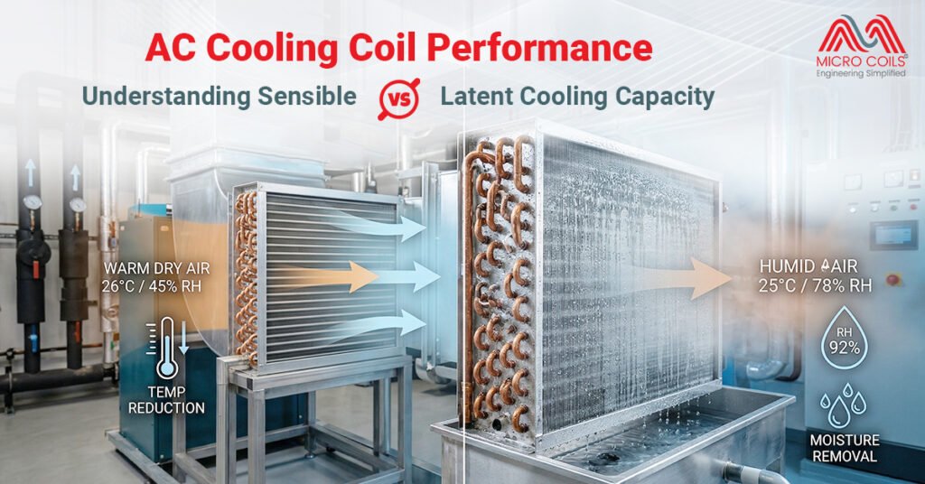
When you walk into a cool, comfortable room on a hot summer day, your AC cooling coil is doing two important jobs at once—lowering the temperature and removing humidity from the air. These two functions represent sensible and latent cooling capacity, and understanding how they work together determines whether your air conditioning system truly keeps you comfortable or just moves air around.
Many people assume air conditioning only cools air, but the reality is more complex. Your comfort depends equally on temperature and humidity levels. A room at 75°F with 80% humidity feels miserable, while the same temperature at 45% humidity feels pleasant. This is where the dual nature of cooling capacity becomes critical for anyone selecting, maintaining, or optimizing HVAC systems.
Sensible cooling capacity refers to the cooling you can actually feel and measure with a thermometer. When your AC cooling coil removes sensible heat, it lowers the air temperature without changing moisture content. This is the straightforward part of air conditioning that most people understand intuitively.
Think of sensible cooling as the difference between air entering your cooling coil at 85°F and leaving at 55°F. That 30-degree temperature drop represents sensible heat removal. The air molecules slow down, the space feels cooler, and your thermometer confirms the change. Every air conditioning system must provide adequate sensible cooling to meet the temperature demands of the space it serves.
Sensible cooling becomes the dominant requirement in dry climates where humidity levels stay naturally low. Desert regions, high-altitude locations, and areas with arid conditions need air conditioning primarily for temperature reduction. The air already contains minimal moisture, so the cooling system focuses its capacity on lowering temperature rather than fighting humidity.
The adiabatic cooling heat exchanger manufacturer in India market recognizes this principle in their designs. Adiabatic systems leverage water evaporation to enhance sensible cooling efficiency, particularly effective in hot, dry conditions where the process doesn’t add problematic humidity. These systems pre-cool air before it reaches the main cooling coil, reducing the sensible load and improving overall system efficiency.
Latent cooling capacity addresses the hidden heat contained in moisture. When your AC cooling coil removes humidity from air, it must extract the latent heat that keeps water in vapor form. This cooling process doesn’t change air temperature directly—instead, it removes moisture that makes air feel sticky and uncomfortable.
The term “latent” means hidden or concealed, and that perfectly describes this type of cooling. You cannot measure latent heat removal with a thermometer. Instead, you measure it through humidity reduction—air enters the coil at 70% relative humidity and exits at 50% relative humidity, even if temperature change is minimal during this specific phase of the process.
Latent cooling happens when water vapor in air contacts the cold surface of your cooling coil. The vapor condenses into liquid water, releasing its latent heat to the coil in the process. This condensed water drips into the drain pan and exits your building through condensate lines. Every pint of water removed from your air represents significant latent cooling capacity at work.
Coastal regions, tropical climates, and humid continental zones require substantial latent cooling capacity. In Mumbai during monsoon season or Chennai in summer, humidity often matters more than temperature for comfort. An AC cooling coil must remove gallons of water daily from indoor air while simultaneously providing sensible cooling.
Your AC cooling coil manages sensible and latent cooling simultaneously through a carefully orchestrated process. Warm, humid air passes over the cold coil surface. The temperature difference between air and coil drives sensible heat transfer, cooling the air. Simultaneously, the coil surface temperature stays below the dew point of the incoming air, causing moisture to condense and removing latent heat.
The coil design directly influences how effectively it balances these two cooling modes. Fin spacing, row depth, and surface area all affect the ratio of sensible to latent cooling. Tightly spaced fins with multiple rows create more surface contact, enhancing both temperature reduction and moisture removal. However, this same configuration increases air resistance and requires more powerful fans to maintain airflow.
Pillow plate manufacturers create specialized heat exchangers using a unique embossed design that increases surface area without traditional fins. These pillow plates form raised patterns that enhance heat transfer while maintaining structural strength. In cooling applications, this design offers advantages for controlling the sensible heat ratio while managing condensate effectively.
The refrigerant temperature inside your cooling coil determines the split between sensible and latent capacity. Colder coil surfaces enhance moisture removal but may overcool air temperature. Warmer coil surfaces prioritize temperature reduction but may leave humidity higher than desired. System designers carefully select refrigerant temperatures and expansion valve settings to achieve the optimal balance for each application.
Manufacturers, including pillow plate manufacturers, engineer cooling equipment with specific SHR targets based on application requirements. The physical design of heat exchangers determines how effectively they balance temperature reduction against moisture removal.
Coil surface temperature represents the primary control variable. Lowering refrigerant temperature increases both sensible and latent capacity, but latent capacity increases more dramatically. The coil surface must drop below the incoming air’s dew point temperature to trigger condensation and moisture removal.
Airflow velocity across the coil affects the balance significantly. Slower airflow allows more contact time between air and cold surfaces, enhancing both heat transfer and condensation. However, excessively slow airflow reduces overall system capacity and may cause comfort problems from inadequate air circulation.
Face area and row depth configuration determine total heat transfer surface available. Multiple-row coils with deep configurations provide more cooling capacity overall and generally enhance latent capacity more than sensible capacity due to progressively colder surfaces in downstream rows.
Selecting the right AC cooling coil configuration requires matching sensible and latent capacity to actual building loads. Engineers perform detailed calculations considering climate data, building construction, occupancy patterns, and equipment heat generation to determine the required SHR.
Healthcare facilities demand precise control over both temperature and humidity. Operating rooms require specific humidity ranges to prevent static electricity and maintain sterile conditions. Patient rooms need comfort cooling that removes moisture without over-drying air. These varying requirements within a single building necessitate multiple AC cooling coil selections with different SHR capabilities.
Manufacturing environments present unique challenges. Electronics assembly requires extremely low humidity to prevent condensation and static damage, demanding systems with low SHR. Food processing facilities need both temperature control and moisture removal to prevent bacterial growth. Textile manufacturing often adds humidity intentionally while removing heat, requiring sensible-focused cooling.
The adiabatic cooling heat exchanger manufacturer in India sector serves markets where outdoor conditions vary dramatically. Pre-cooling ambient air through water evaporation reduces the mechanical cooling load while naturally addressing part of the sensible requirement. This hybrid approach optimizes energy efficiency while maintaining the precise SHR needed for comfort.
Dirty AC cooling coils lose both sensible and latent capacity, but latent capacity suffers more dramatically. Dirt and debris on coil surfaces insulate against heat transfer, reducing temperature change effectiveness. More critically, contamination blocks the intimate air-to-surface contact necessary for moisture condensation.
When coil surfaces become fouled, air passes over rather than through the fin spaces. This reduced contact prevents adequate cooling and almost eliminates dehumidification. The system runs longer to achieve temperature setpoints while never properly removing moisture. Energy consumption soars while comfort plummets.
Regular cleaning restores designed capacity ratios. Professional coil cleaning removes accumulated dirt, biological growth, and mineral deposits. The restored surface area allows proper heat transfer and moisture condensation. Systems often show dramatic performance improvements immediately after thorough cleaning.
Condensate drainage maintenance matters equally for latent capacity preservation. Clogged drain lines cause water to back up into the coil area. This standing water becomes a breeding ground for mold and bacteria that further contaminate coil surfaces. Proper drainage ensures removed moisture exits the system rather than recirculating.
Air filter maintenance protects cooling coils from contamination. Clean filters capture airborne particles before they reach coil surfaces. However, filters themselves create resistance to airflow. Excessively dirty filters reduce air volume across the coil, altering the designed sensible-latent balance and reducing both capacity types.
Every building has a unique fingerprint of sensible and latent loads determined by its purpose, location, and construction. Understanding these loads allows proper AC cooling coil selection that delivers comfort efficiently. Mismatched systems waste energy while failing to maintain ideal conditions.
Calculate sensible loads by accounting for heat gain through walls, roofs, windows, and floors, plus heat generated by lighting, equipment, and occupants. These calculations vary with building orientation, insulation quality, window size and type, and internal equipment density.
Latent loads come primarily from outdoor air infiltration, occupant respiration and perspiration, and moisture-generating processes like cooking or manufacturing. High-traffic areas with frequently opened doors carry substantial latent loads from humid outdoor air entering continuously.
System designers use psychrometric analysis to plot these loads and determine the required cooling coil performance. The charts show how air conditions change as it passes through the coil, revealing the necessary sensible and latent capacity split. This analytical approach prevents guesswork and ensures optimal system selection.
The adiabatic cooling heat exchanger manufacturer in India market provides solutions particularly suited to hot, dry climates where sensible loads dominate. These systems reduce mechanical cooling requirements through natural evaporative processes, lowering operating costs while maintaining designed capacity ratios.
Advanced control systems now monitor both temperature and humidity in real-time, adjusting AC cooling coil operation to maintain optimal conditions. These smart systems learn building patterns and anticipate loads rather than simply reacting to current conditions. The result is improved comfort with reduced energy consumption.
Variable refrigerant flow technology allows precise capacity modulation. Instead of simple on-off cycling, these systems adjust cooling output continuously. This capability enables dynamic SHR adjustment as conditions change throughout the day or season. Buildings in mixed climates particularly benefit from this flexibility.
Dedicated outdoor air systems separate ventilation from space conditioning. Fresh air receives treatment specifically designed for its high latent content, while recirculated air gets tempered for sensible loads. This approach optimizes each cooling coil for its specific duty rather than compromising with a one-size-fits-all solution.
Enhanced materials from pillow plate manufacturers and other heat exchanger innovators improve heat transfer efficiency. Better thermal conductivity and increased surface area allow smaller, lighter coils to deliver equivalent capacity. These advances enable more compact equipment with lower refrigerant charges and reduced environmental impact.
Understanding the difference between sensible and latent cooling capacity transforms how you think about air conditioning. Your AC cooling coil isn’t just a temperature-changing device—it’s a sophisticated component managing the complex relationship between heat and moisture that defines human comfort. Proper selection, installation, and maintenance of these systems ensures efficient operation that keeps spaces comfortable regardless of outdoor conditions or internal loads.
Yes, you can enhance latent capacity by lowering the refrigerant temperature through thermostat adjustments or adding a subcooling circuit. Installing a bypass damper reduces airflow slightly, increasing coil contact time for better moisture removal. However, these modifications have limits—severely undersized systems require coil replacement for adequate dehumidification performance.
Your AC cooling coil has excessive sensible capacity relative to latent capacity for your climate. The system reaches temperature setpoints quickly and shuts off before removing sufficient moisture. Oversized equipment, high airflow settings, or warm refrigerant temperatures cause this imbalance, requiring adjustments to fan speed or thermostat settings for proper dehumidification.
Stainless steel systems are more corrosion-resistant but can suffer from stress corrosion cracking in chloride environments – watch for hairline cracks near welds. Exotic materials like titanium or Hastelloy are highly resistant to chemical attack but may show different thermal expansion behaviors. Adjust your baseline parameters accordingly. The key is understanding your specific material’s vulnerabilities and focusing inspection efforts there. Document material specifications when purchasing from pillow plate manufacturers so your maintenance team knows exactly what they’re working with.
Adiabatic cooling systems from an adiabatic cooling heat exchanger manufacturer in India handle sensible loads through water evaporation, reducing the burden on your mechanical AC cooling coil. This allows the main coil to focus capacity on latent removal. The approach works excellently in dry climates but adds humidity in already-moist environments, potentially worsening latent loads.
Commercial kitchens require SHR between 0.60 and 0.70 due to massive latent loads from cooking, dishwashing, and steam. Standard AC cooling coils designed for office spaces with SHR around 0.80 fail miserably in food service. Specify equipment explicitly rated for high-moisture environments, and consider dedicated makeup air systems to handle ventilation loads separately from space conditioning.
Yes, designs from pillow plate manufacturers provide enhanced surface area and turbulent flow patterns that improve both sensible and latent heat transfer. The embossed structure promotes better condensation while maintaining efficient temperature exchange. This design flexibility allows engineers to optimize cooling coils for specific SHR requirements without dramatically increasing physical size or refrigerant charge amounts.
AC Cooling Coil Performance: Understanding Sensible vs. Latent Cooling Capacity Read More »
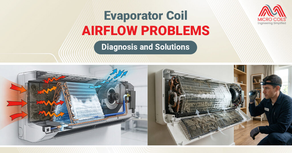
Your air conditioning system works hard to keep your home comfortable, but when airflow problems develop around the evaporator coil, everything can go wrong. You might notice weak airflow from your vents, ice forming on your AC unit, or your energy bills suddenly climbing. These issues often trace back to the evaporator coil—the critical component responsible for cooling the air in your home.
Understanding how to diagnose and fix airflow problems can save you from costly repairs and prevent complete system failure. Let’s explore the common issues, warning signs, and practical solutions you can implement today.
The evaporator coil is the indoor component of your air conditioning system. Think of it as a network of thin metal tubes, usually made of copper or aluminum, with fins attached. Cold refrigerant flows through these tubes, and as warm air from your home passes over the coil, heat transfers from the air to the refrigerant. This process cools the air, which then circulates back into your living spaces.
For this heat exchange to work efficiently, air must flow freely across the AC evaporator coil surface. When airflow becomes restricted or blocked, the entire cooling process breaks down. The refrigerant inside the coil gets too cold, moisture in the air freezes on the surface, and your system struggles to cool your home.
Refrigeration coils, which include evaporator coils, are designed with specific airflow requirements. Most residential systems need between 350-450 cubic feet per minute of air per ton of cooling capacity. When airflow drops below this range, problems multiply quickly. The coil cannot absorb heat properly, your compressor works overtime, and component wear accelerates dramatically.
Before diving into diagnosis, you need to recognize the symptoms. Ice formation is one of the most obvious signs if you see ice or frost on the refrigerant lines or around the indoor unit, airflow is likely restricted. The coil gets too cold because warm air isn’t flowing over it fast enough to absorb the refrigerant’s coldness.
Weak air from vents is another clear indicator. When you place your hand near a supply vent, the air should blow with noticeable force. Weak or barely perceptible airflow indicates a problem upstream at the evaporator coil. You might also notice that some rooms feel comfortable while others remain warm, suggesting uneven air distribution caused by restricted flow.
Your AC running for extended periods without reaching the target temperature is a major red flag. This happens because restricted airflow prevents efficient heat exchange. The system cycles on and stays on, struggling to achieve what should be a simple task. Meanwhile, your energy consumption skyrockets as the equipment works overtime to achieve minimal cooling results.
In severe cases, the AC blows warm or room-temperature air because the evaporator coil can’t properly cool the air passing over it. Strange noises like whistling, hissing, or reduced blower motor sounds can also indicate airflow restrictions. These sounds often result from air forcing its way through narrowed passages or components struggling against increased resistance.
Finding the exact cause of airflow problems requires a systematic approach. Here’s how to diagnose issues with your AC evaporator coil and related components:
Your air filter serves as the first line of defense for your evaporator coil, but it can also become the primary cause of airflow problems. The filter sits between your return air ducts and the evaporator coil, capturing dust, pollen, pet dander, and other airborne particles before they reach the delicate coil fins.
When filters become clogged, they create a barrier that chokes off airflow. Imagine trying to breathe through a cloth that becomes progressively thicker—that’s what your system experiences with a dirty filter. The blower motor works harder, pulling against increasing resistance, while less air actually makes it through to cool your home.
Locate your air filter by checking common spots: inside return air grilles on walls or ceilings, within the blower compartment of your air handler, or in a dedicated filter slot near the unit. Remove the filter and hold it up to a light source. If you cannot see light passing through easily, the filter is blocking airflow and needs immediate replacement.
Replacement frequency depends on several factors. Homes with pets, high dust levels, or family members with allergies need more frequent changes. Standard one-inch filters typically require monthly replacement during heavy use seasons like summer and winter. Thicker pleated filters, ranging from four to five inches, can last three to six months before airflow restriction becomes problematic.
The blower motor and fan assembly push air across your evaporator coil. When this component underperforms, even a perfectly clean coil cannot cool your home effectively. Listen carefully when your system runs—the blower should produce a steady, consistent sound without grinding, squealing, or labored operation.
A dirty blower wheel is surprisingly common and dramatically impacts performance. Dust accumulation on the wheel’s blades adds weight and creates an unbalanced, inefficient fan. This buildup can reduce airflow by thirty to fifty percent, forcing your system to run longer while achieving less cooling. Accessing the blower wheel usually requires removing a panel on your air handler, where you can visually inspect for dust and debris coating the fan blades.
Check your thermostat settings to ensure the fan operates on “auto” mode rather than continuous low speed. While running the fan continuously might seem beneficial for air circulation, it can actually reduce cooling efficiency and mask airflow problems at the AC evaporator coil. The auto setting ensures the blower runs at full speed during cooling cycles, maximizing air movement when it matters most.
Older systems with belt-driven blowers require additional attention. Inspect the belt connecting the motor to the blower wheel for cracks, fraying, or excessive wear. A loose or damaged belt slips rather than transferring full power, reducing the volume of air pushed across your refrigeration coils.
Your ductwork forms the pathway between your evaporator coil and your living spaces. Problems in this network can mimic or compound evaporator coil airflow issues. Start by examining accessible duct sections in basements, attics, or crawlspaces. Look for disconnected joints where sections have separated, holes or tears in flexible ducting, or crushed rigid ducts that restrict airflow.
Pay special attention to supply vents throughout your home. Furniture placement, curtains, or deliberately closed vents in unused rooms force air to redistribute through remaining openings, creating pressure imbalances that affect overall system performance. Each vent should have clear space around it for unrestricted air delivery.
Return air vents deserve equal scrutiny. These vents pull warm air from your home back to the evaporator coil for cooling. Blocked return vents starve the system of air to process, creating a bottleneck that reduces flow across the coil regardless of its condition. Ensure sofas, beds, or storage items don’t obstruct these critical intake points.
Temperature differences between supply and return air provide diagnostic clues. When your system runs properly, supply air should measure fifteen to twenty degrees cooler than return air. Smaller temperature differences suggest inadequate heat exchange at the evaporator coil, often caused by restricted airflow preventing proper cooling.
Once you’ve identified the problem, implementing the right solution restores efficiency and comfort to your home. Different issues require different approaches, from simple maintenance tasks you can handle yourself to situations requiring professional expertise.
A dirty evaporator coil is the most common airflow problem homeowners face. Dust and debris create an insulating layer that blocks air passage and prevents efficient heat transfer. The solution depends on contamination severity and your comfort level with DIY maintenance.
For light surface dust, turn off all power to your AC system at both the thermostat and circuit breaker. Use a soft brush attachment on your vacuum cleaner to gently remove loose debris from the coil fins. Work slowly and carefully—the aluminum or copper fins bend easily, and damaged fins further restrict airflow. Vacuum from the air-entry side of the coil, pulling debris away rather than pushing it deeper into the fin spaces.
Heavy contamination, thick mold growth, or sticky residues require professional attention. HVAC technicians have specialized equipment, powerful cleaning agents, and the experience to thoroughly clean refrigeration coils without causing damage. They can also straighten bent fins, check refrigerant levels, and verify that cleaning has restored proper airflow and system performance.
Replacing a clogged air filter is the fastest, easiest fix for airflow problems. Purchase the correct size filter by checking the dimensions printed on your current filter’s cardboard frame. Common residential sizes include 16×20, 20×25, and 16×25 inches, with thickness ranging from one to five inches. Installing the wrong size allows unfiltered air to bypass the filter, sending contaminants directly to your evaporator coil.
Create a filter replacement schedule based on your home’s conditions. Set phone or calendar reminders to check filters monthly during peak cooling and heating seasons. Homes with pets, ongoing construction nearby, or family members with respiratory sensitivities may need more frequent changes. Keep several spare filters on hand so you can swap them immediately when needed rather than delaying until you purchase replacements.
When your blower motor or fan assembly causes airflow problems, several approaches can restore performance. Cleaning a dirty blower wheel makes a dramatic difference in many cases. After shutting off power completely, access the blower compartment and carefully remove the blower assembly if possible. Use a brush and vacuum to remove dust buildup from the wheel blades, paying attention to both sides of each blade. Some technicians use mild detergent and water for stubborn grime, but ensure everything dries completely before reassembly and power restoration.
Belt-driven systems need proper belt tension and condition. A loose belt slips on the pulleys, reducing the speed at which the blower wheel spins and decreasing airflow across your refrigeration coils. Tightening or replacing worn belts restores full power transfer. Most systems include an adjustment mechanism that allows tension modification without replacing components.
Ductwork problems range from simple fixes to complex renovations. Disconnected joints often need nothing more than professional-grade metal tape or mastic sealant to restore airtight connections. Never use standard cloth duct tape for HVAC repairs—despite the name, it fails quickly in the temperature extremes and humidity levels inside ductwork.
Crushed or kinked flexible ducts should be replaced or rerouted. These damaged sections create permanent restrictions that rob your system of airflow capacity. In finished areas where ductwork runs inside walls or ceilings, professional assessment helps determine whether repair justifies the cost of opening and repairing structural elements.
Some airflow problems exceed typical homeowner capabilities or safety comfort levels. Refrigerant issues, electrical problems, and major component failures require certified technicians with proper tools and training. Similarly, if you’ve replaced filters, cleaned accessible components, and verified duct integrity without resolving airflow problems, professional diagnosis can identify hidden issues.
Regular professional maintenance prevents many airflow problems before they develop. Annual tune-ups include thorough evaporator coil inspection and cleaning, refrigerant level verification, electrical connection testing, and comprehensive system performance evaluation. This preventive approach catches small issues before they become major failures, extends equipment life, and maintains peak efficiency throughout the cooling season.
Prevention is always easier and less expensive than repair. Simple habits protect your AC evaporator coil and maintain optimal airflow year after year. Change or clean air filters on a regular schedule without exception. This single action prevents the majority of airflow problems and protects your evaporator coil from contamination that degrades performance and shortens lifespan.
Keep the area around your indoor air handler clean and uncluttered. Dust, pet hair, and debris near the unit get pulled into the return air stream and eventually accumulate on your refrigeration coils. Regular vacuuming and dusting in mechanical spaces reduces the contamination load your system must handle.
Schedule annual professional maintenance before each cooling season begins. Spring tune-ups ensure your system enters the demanding summer months in peak condition, with clean coils, proper refrigerant levels, and optimized airflow. This investment pays dividends through lower energy consumption, fewer emergency repairs, and extended equipment life.
Nighttime freezing occurs because cooler outdoor temperatures and reduced indoor heat generation cause your evaporator coil to drop below freezing. During the day, sunlight, appliances, and activity generate enough heat to prevent freezing even with minor airflow restrictions.
Strong airflow with poor cooling indicates your AC evaporator coil receives adequate air but isn’t cooling it. This typically signals low refrigerant levels, a malfunctioning compressor, or expansion valve failure rather than airflow blockage requiring professional diagnosis.
Stainless steel systems are more corrosion-resistant but can suffer from stress corrosion cracking in chloride environments – watch for hairline cracks near welds. Exotic materials like titanium or Hastelloy are highly resistant to chemical attack but may show different thermal expansion behaviors. Adjust your baseline parameters accordingly. The key is understanding your specific material’s vulnerabilities and focusing inspection efforts there. Document material specifications when purchasing from pillow plate manufacturers so your maintenance team knows exactly what they’re working with.
Yes, excessive humidity above 60% causes rapid condensation on your evaporator coil that can freeze and block airflow. High moisture also promotes mold growth on refrigeration coils, creating sticky buildup that traps dust and restricts air passage significantly.
Water overflow typically indicates a frozen evaporator coil that melts during off cycles, overwhelming the drain pan. Ice forms from restricted airflow, then melts rapidly when the system stops, producing more water than the pan handles properly.
Temporary improvement after shutdown indicates ice buildup on your AC evaporator coil during operation. The ice melts while off, restoring airflow briefly. This pattern points to underlying issues like low refrigerant or dirty refrigeration coils causing progressive freezing.
Evaporator Coil Airflow Problems: Diagnosis and Solutions Read More »