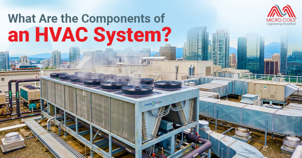

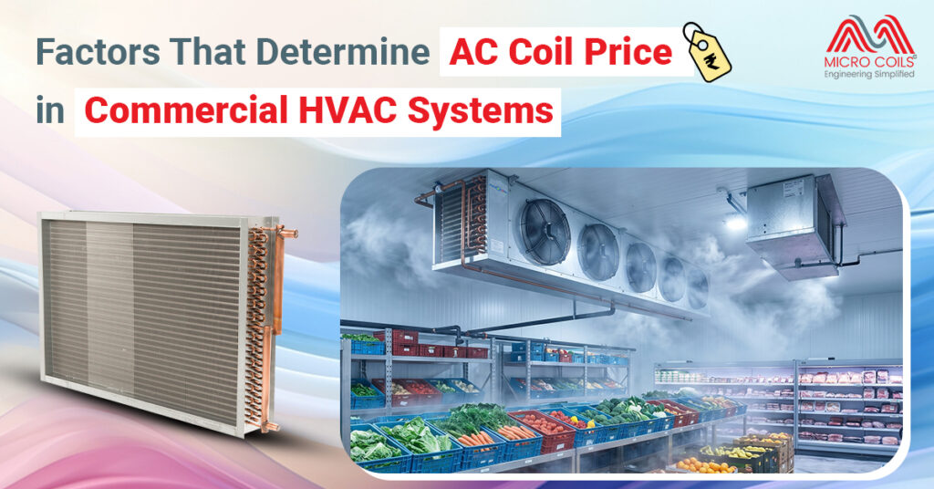
Factors That Determine AC Coil Price in Commercial HVAC Systems
Commercial HVAC systems depend heavily on coil performance for efficient heating and cooling operations. Coil selection affects airflow, heat transfer, energy usage, and long-term maintenance costs. Different industries require different coil configurations based on operating conditions and cooling demand. Because of this, pricing can vary significantly across commercial applications.
The AC coil price in large HVAC systems is influenced by several technical and material-related factors. Coil size, metal quality, design complexity, and operating pressure all contribute to the final cost. Environmental conditions also affect the type of coil required for a specific installation. Buyers often compare durability, efficiency, and maintenance requirements before making a purchasing decision.
Coil Material
Material selection directly impacts coil durability and thermal performance. Copper coils usually cost more because they offer stronger heat transfer efficiency and easier repair options. Aluminum coils are lighter and more affordable, making them suitable for cost-sensitive projects. Corrosion resistance also differs depending on the metal composition.
Coils installed in coastal or industrial environments require stronger protective properties. Exposure to moisture, chemicals, and pollutants can reduce coil lifespan rapidly. Some manufacturers apply special coatings to improve corrosion resistance in harsh conditions. These additional protective layers increase manufacturing and installation costs.
Coil Size and Capacity
Larger commercial buildings require coils with higher cooling capacities. Bigger coils contain more tubing and wider surface areas to manage greater heat loads effectively. Increased material usage naturally raises production expenses. High-capacity systems also demand stronger structural support and airflow management.
Cooling demand varies widely between offices, factories, hospitals, and retail spaces. A small office setup will not require the same coil dimensions as a manufacturing plant. System tonnage, airflow volume, and occupancy levels influence final sizing decisions. Incorrect sizing can reduce efficiency and increase long-term operating costs.
Coil Design and Construction
Coil construction affects both system performance and manufacturing complexity. Some coils use multiple rows and enhanced fin designs to improve heat exchange efficiency. Advanced configurations support better airflow and temperature control under demanding conditions. Complex engineering increases fabrication time and production cost.
The AC cooling coil used in commercial HVAC systems may also include custom-built configurations. Certain applications require specialized tube spacing, pressure ratings, or fin density adjustments. Data centers and pharmaceutical facilities often demand precision cooling performance. Customized coil construction usually increases overall project expenditure.
Type of Commercial Application
Different industries place different performance demands on HVAC systems. Hospitals, laboratories, and food processing facilities require stricter temperature and humidity control standards. These environments often need premium-grade coil systems with advanced efficiency capabilities. Specialized requirements directly affect final equipment pricing.
Commercial offices and retail spaces may prioritize energy efficiency and operating cost reduction instead. Industrial facilities often focus more on durability and heavy-duty performance. HVAC coil selection changes depending on operating hours, indoor conditions, and ventilation demands. Application-specific engineering adds another layer to pricing variation.
Manufacturing and Brand Standards
Manufacturing quality plays a major role in coil pricing. Established brands often use better fabrication methods, stronger quality checks, and advanced testing procedures. Higher production standards improve reliability and reduce the chances of operational failure. Premium manufacturing usually comes with higher upfront costs.
Certification requirements can also influence pricing in commercial projects. Many industries require HVAC equipment that complies with safety and energy efficiency regulations. Certified products often undergo additional testing before approval. Compliance with international standards increases manufacturing complexity and overall cost.
Factors That Commonly Increase Coil Cost
Several conditions can push commercial coil prices higher during procurement and installation stages. Material upgrades, custom engineering, and environmental protection features all contribute to pricing changes. System performance expectations also influence final product selection. Common cost-driving factors include:
- Increased coil thickness for higher durability
- Protective coatings for corrosion resistance
- Custom dimensions for large commercial spaces
- High-pressure operation requirements
- Energy-efficient fin and tube configurations
- Imported raw material pricing fluctuations
- Specialized manufacturing for industrial environments
Installation conditions can also increase project expenses significantly. Complex duct layouts and limited installation space may require customized coil designs. Transportation costs for oversized commercial equipment can further affect pricing. Long-term maintenance accessibility is another factor considered during system planning.
Energy Efficiency Requirements
Energy-efficient HVAC systems often use advanced coil technologies to reduce power consumption. Improved heat transfer performance allows systems to cool spaces faster with lower energy usage. High-efficiency coils may include enhanced fin surfaces and optimized refrigerant pathways. These design improvements generally increase manufacturing costs.
Many businesses now prioritize lower operating costs and energy compliance standards. Efficient systems may cost more initially but reduce utility expenses over time. Long-term savings often justify the higher investment in premium coil designs.
Outdoor Environmental Conditions
Environmental exposure has a strong impact on coil selection in commercial HVAC installations. Coastal regions expose equipment to salt-heavy air, while industrial zones may contain chemical pollutants and airborne contaminants. Standard coils may deteriorate quickly under such conditions. More durable designs become necessary in challenging environments.
The AC condenser coil installed outdoors faces continuous exposure to weather fluctuations and debris accumulation. Rain, dust, heat, and humidity can affect long-term operating efficiency. Protective coatings and heavy-duty construction improve durability in demanding outdoor conditions. These enhancements increase both manufacturing and replacement costs.
How to Prevent Overpaying for the AC Coil Price?
- Many buyers focus only on the initial quotation when comparing HVAC coil costs. That approach often leads to poor purchasing decisions. A lower-priced coil may require frequent repairs, deliver weak performance, or consume more energy over time. On the other hand, expensive models are not always necessary for every commercial application.
- Start by understanding the exact cooling requirement of the building before requesting quotations. Coil size, airflow demand, refrigerant type, and operating conditions should all be clearly defined. Oversized coils increase equipment and installation expenses unnecessarily. Undersized units create efficiency problems and higher operating stress.
- Comparing specifications matters more than comparing price tags alone. Two coils may appear similar externally while using completely different tube thickness, fin density, or material quality internally. Request detailed technical sheets from multiple suppliers before making a decision. Missing specifications often hide long-term performance compromises.
- Material selection should match the installation environment instead of blindly choosing premium options. Coastal areas may genuinely require corrosion-resistant coatings and heavy-duty construction. A standard indoor commercial office setup may not need those costly upgrades. Paying for unnecessary protective features increases project expenditure without delivering practical value.
- Buyers should also evaluate energy performance carefully. Efficient coils reduce electricity consumption and lower operating costs across the system lifecycle. Some low-cost products create higher utility expenses because of weak heat transfer efficiency. Short-term savings can quickly disappear through increased power usage.
- Installation costs deserve equal attention during budgeting. Certain coil designs require customized duct modifications, additional support structures, or complex refrigerant connections. These hidden expenses are often overlooked during procurement discussions. Clarifying installation requirements early prevents unexpected project cost escalation later.
- Vendor reputation plays a major role in long-term value. Suppliers with reliable after-sales support, warranty coverage, and consistent manufacturing quality usually deliver better operational reliability. Extremely cheap products from unknown manufacturers may increase maintenance frequency and replacement risk. Careful technical evaluation, not aggressive price negotiation alone, helps prevent overpaying for commercial HVAC coils.
Conclusion
Commercial HVAC coil pricing depends on a combination of technical, environmental, and operational factors. Material quality, system capacity, design complexity, and application type all contribute to final costs. Pricing differences become more noticeable in large-scale or specialized installations. Choosing the right coil requires balancing efficiency, durability, and long-term performance needs.
Cost should never be evaluated in isolation during commercial HVAC planning. Lower-priced coils may lead to higher maintenance expenses and reduced operational efficiency over time. Durable and properly engineered coils often deliver better long-term value in demanding environments. Careful selection helps improve system reliability, energy performance, and equipment lifespan.
Commercial HVAC coils usually last between 10 to 20 years depending on operating conditions, maintenance quality, and environmental exposure. Systems installed in polluted or coastal areas may experience faster wear due to corrosion and debris accumulation.
Minor leaks, fin damage, or connection issues can often be repaired by trained technicians. Severe corrosion, repeated refrigerant leakage, or structural damage usually makes replacement the more practical long-term solution.
Restricted airflow, refrigerant imbalance, dirty filters, or blower issues can cause coils to freeze. Ice formation reduces cooling performance and places additional stress on compressors and other connected components.
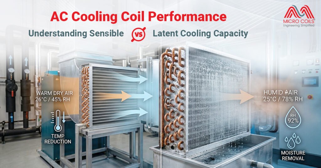
Yes, coils help remove excess moisture from indoor air during cooling cycles. Proper moisture removal improves indoor comfort and helps prevent issues like condensation buildup, mold growth, and damp indoor conditions.
Routine cleaning, airflow inspection, fin straightening, and refrigerant monitoring help maintain coil efficiency. Scheduled maintenance also helps identify performance issues early before they develop into larger operational problems.
Factors That Determine AC Coil Price in Commercial HVAC Systems Read More »