
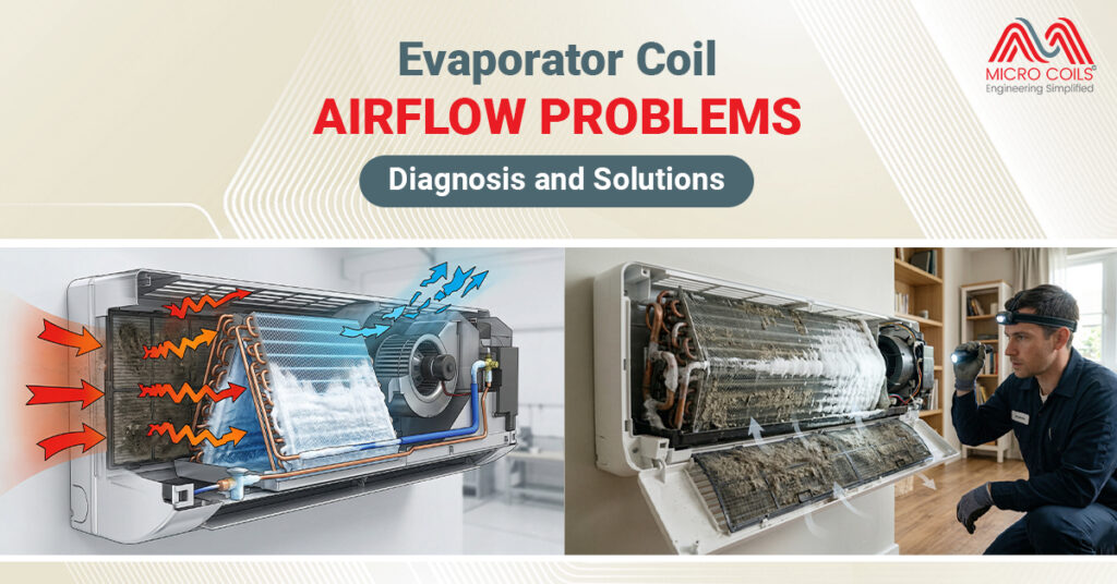
Evaporator Coil Airflow Problems: Diagnosis and Solutions
Your air conditioning system works hard to keep your home comfortable, but when airflow problems develop around the evaporator coil, everything can go wrong. You might notice weak airflow from your vents, ice forming on your AC unit, or your energy bills suddenly climbing. These issues often trace back to the evaporator coil—the critical component responsible for cooling the air in your home.
Understanding how to diagnose and fix airflow problems can save you from costly repairs and prevent complete system failure. Let’s explore the common issues, warning signs, and practical solutions you can implement today.
What Is an Evaporator Coil and Why Does Airflow Matter?
The evaporator coil is the indoor component of your air conditioning system. Think of it as a network of thin metal tubes, usually made of copper or aluminum, with fins attached. Cold refrigerant flows through these tubes, and as warm air from your home passes over the coil, heat transfers from the air to the refrigerant. This process cools the air, which then circulates back into your living spaces.
For this heat exchange to work efficiently, air must flow freely across the AC evaporator coil surface. When airflow becomes restricted or blocked, the entire cooling process breaks down. The refrigerant inside the coil gets too cold, moisture in the air freezes on the surface, and your system struggles to cool your home.
Refrigeration coils, which include evaporator coils, are designed with specific airflow requirements. Most residential systems need between 350-450 cubic feet per minute of air per ton of cooling capacity. When airflow drops below this range, problems multiply quickly. The coil cannot absorb heat properly, your compressor works overtime, and component wear accelerates dramatically.
Common Warning Signs of Evaporator Coil Airflow Problems
Before diving into diagnosis, you need to recognize the symptoms. Ice formation is one of the most obvious signs if you see ice or frost on the refrigerant lines or around the indoor unit, airflow is likely restricted. The coil gets too cold because warm air isn’t flowing over it fast enough to absorb the refrigerant’s coldness.
Weak air from vents is another clear indicator. When you place your hand near a supply vent, the air should blow with noticeable force. Weak or barely perceptible airflow indicates a problem upstream at the evaporator coil. You might also notice that some rooms feel comfortable while others remain warm, suggesting uneven air distribution caused by restricted flow.
Your AC running for extended periods without reaching the target temperature is a major red flag. This happens because restricted airflow prevents efficient heat exchange. The system cycles on and stays on, struggling to achieve what should be a simple task. Meanwhile, your energy consumption skyrockets as the equipment works overtime to achieve minimal cooling results.
In severe cases, the AC blows warm or room-temperature air because the evaporator coil can’t properly cool the air passing over it. Strange noises like whistling, hissing, or reduced blower motor sounds can also indicate airflow restrictions. These sounds often result from air forcing its way through narrowed passages or components struggling against increased resistance.
Detailed Diagnosis: Step-by-Step Airflow Problem Identification
Finding the exact cause of airflow problems requires a systematic approach. Here’s how to diagnose issues with your AC evaporator coil and related components:
Visual Inspection of the Evaporator Coil
- Turn off your AC system completely at the thermostat and breaker box before beginning any inspection for safety
- Locate your evaporator coil, typically found inside the air handler unit in your basement, attic, or utility closet
- Remove the access panel using a screwdriver; most panels are held by a few screws and lift away easily
- Examine the coil fins closely using a flashlight; look for visible dust, dirt, pet hair, or debris accumulation between the thin metal fins
- Check for fin damage such as bent, crushed, or flattened fins that block air passages; even partially bent fins reduce airflow significantly
- Look for signs of mold or mildew which appears as black, green, or white patches on the coil surface; mold not only blocks airflow but also affects indoor air quality
- Inspect the drain pan beneath the coil for standing water, rust, or biological growth which indicates drainage problems that can contribute to airflow issues
- Examine the insulation around the evaporator coil cabinet for deterioration, gaps, or moisture damage that could affect system performance
- Check the spacing between fins by gently running your finger along them; fins should be evenly spaced and not compressed together
- Look for corrosion or pitting on the coil surface, especially if you live in a coastal area or use harsh cleaning chemicals nearby
- Verify the coil is level inside its housing; a tilted coil can affect both airflow patterns and condensate drainage
- Inspect refrigerant connections for any signs of oil residue which indicates potential leaks affecting system performance
The Importance of Air Filter Impact
Your air filter serves as the first line of defense for your evaporator coil, but it can also become the primary cause of airflow problems. The filter sits between your return air ducts and the evaporator coil, capturing dust, pollen, pet dander, and other airborne particles before they reach the delicate coil fins.
When filters become clogged, they create a barrier that chokes off airflow. Imagine trying to breathe through a cloth that becomes progressively thicker—that’s what your system experiences with a dirty filter. The blower motor works harder, pulling against increasing resistance, while less air actually makes it through to cool your home.
Locate your air filter by checking common spots: inside return air grilles on walls or ceilings, within the blower compartment of your air handler, or in a dedicated filter slot near the unit. Remove the filter and hold it up to a light source. If you cannot see light passing through easily, the filter is blocking airflow and needs immediate replacement.
Replacement frequency depends on several factors. Homes with pets, high dust levels, or family members with allergies need more frequent changes. Standard one-inch filters typically require monthly replacement during heavy use seasons like summer and winter. Thicker pleated filters, ranging from four to five inches, can last three to six months before airflow restriction becomes problematic.
Evaluating Blower Motor Performance
The blower motor and fan assembly push air across your evaporator coil. When this component underperforms, even a perfectly clean coil cannot cool your home effectively. Listen carefully when your system runs—the blower should produce a steady, consistent sound without grinding, squealing, or labored operation.
A dirty blower wheel is surprisingly common and dramatically impacts performance. Dust accumulation on the wheel’s blades adds weight and creates an unbalanced, inefficient fan. This buildup can reduce airflow by thirty to fifty percent, forcing your system to run longer while achieving less cooling. Accessing the blower wheel usually requires removing a panel on your air handler, where you can visually inspect for dust and debris coating the fan blades.
Check your thermostat settings to ensure the fan operates on “auto” mode rather than continuous low speed. While running the fan continuously might seem beneficial for air circulation, it can actually reduce cooling efficiency and mask airflow problems at the AC evaporator coil. The auto setting ensures the blower runs at full speed during cooling cycles, maximizing air movement when it matters most.
Older systems with belt-driven blowers require additional attention. Inspect the belt connecting the motor to the blower wheel for cracks, fraying, or excessive wear. A loose or damaged belt slips rather than transferring full power, reducing the volume of air pushed across your refrigeration coils.
Ductwork Considerations
Your ductwork forms the pathway between your evaporator coil and your living spaces. Problems in this network can mimic or compound evaporator coil airflow issues. Start by examining accessible duct sections in basements, attics, or crawlspaces. Look for disconnected joints where sections have separated, holes or tears in flexible ducting, or crushed rigid ducts that restrict airflow.
Pay special attention to supply vents throughout your home. Furniture placement, curtains, or deliberately closed vents in unused rooms force air to redistribute through remaining openings, creating pressure imbalances that affect overall system performance. Each vent should have clear space around it for unrestricted air delivery.
Return air vents deserve equal scrutiny. These vents pull warm air from your home back to the evaporator coil for cooling. Blocked return vents starve the system of air to process, creating a bottleneck that reduces flow across the coil regardless of its condition. Ensure sofas, beds, or storage items don’t obstruct these critical intake points.
Temperature differences between supply and return air provide diagnostic clues. When your system runs properly, supply air should measure fifteen to twenty degrees cooler than return air. Smaller temperature differences suggest inadequate heat exchange at the evaporator coil, often caused by restricted airflow preventing proper cooling.
Practical Solutions for Common Airflow Problems
Once you’ve identified the problem, implementing the right solution restores efficiency and comfort to your home. Different issues require different approaches, from simple maintenance tasks you can handle yourself to situations requiring professional expertise.
Addressing Dirty Evaporator Coils
A dirty evaporator coil is the most common airflow problem homeowners face. Dust and debris create an insulating layer that blocks air passage and prevents efficient heat transfer. The solution depends on contamination severity and your comfort level with DIY maintenance.
For light surface dust, turn off all power to your AC system at both the thermostat and circuit breaker. Use a soft brush attachment on your vacuum cleaner to gently remove loose debris from the coil fins. Work slowly and carefully—the aluminum or copper fins bend easily, and damaged fins further restrict airflow. Vacuum from the air-entry side of the coil, pulling debris away rather than pushing it deeper into the fin spaces.
Heavy contamination, thick mold growth, or sticky residues require professional attention. HVAC technicians have specialized equipment, powerful cleaning agents, and the experience to thoroughly clean refrigeration coils without causing damage. They can also straighten bent fins, check refrigerant levels, and verify that cleaning has restored proper airflow and system performance.
Solving Filter-Related Problems
Replacing a clogged air filter is the fastest, easiest fix for airflow problems. Purchase the correct size filter by checking the dimensions printed on your current filter’s cardboard frame. Common residential sizes include 16×20, 20×25, and 16×25 inches, with thickness ranging from one to five inches. Installing the wrong size allows unfiltered air to bypass the filter, sending contaminants directly to your evaporator coil.
Create a filter replacement schedule based on your home’s conditions. Set phone or calendar reminders to check filters monthly during peak cooling and heating seasons. Homes with pets, ongoing construction nearby, or family members with respiratory sensitivities may need more frequent changes. Keep several spare filters on hand so you can swap them immediately when needed rather than delaying until you purchase replacements.
Restoring Blower Motor Function
When your blower motor or fan assembly causes airflow problems, several approaches can restore performance. Cleaning a dirty blower wheel makes a dramatic difference in many cases. After shutting off power completely, access the blower compartment and carefully remove the blower assembly if possible. Use a brush and vacuum to remove dust buildup from the wheel blades, paying attention to both sides of each blade. Some technicians use mild detergent and water for stubborn grime, but ensure everything dries completely before reassembly and power restoration.
Belt-driven systems need proper belt tension and condition. A loose belt slips on the pulleys, reducing the speed at which the blower wheel spins and decreasing airflow across your refrigeration coils. Tightening or replacing worn belts restores full power transfer. Most systems include an adjustment mechanism that allows tension modification without replacing components.
Correcting Ductwork Issues
Ductwork problems range from simple fixes to complex renovations. Disconnected joints often need nothing more than professional-grade metal tape or mastic sealant to restore airtight connections. Never use standard cloth duct tape for HVAC repairs—despite the name, it fails quickly in the temperature extremes and humidity levels inside ductwork.
Crushed or kinked flexible ducts should be replaced or rerouted. These damaged sections create permanent restrictions that rob your system of airflow capacity. In finished areas where ductwork runs inside walls or ceilings, professional assessment helps determine whether repair justifies the cost of opening and repairing structural elements.
When to Call Professional Help?
Some airflow problems exceed typical homeowner capabilities or safety comfort levels. Refrigerant issues, electrical problems, and major component failures require certified technicians with proper tools and training. Similarly, if you’ve replaced filters, cleaned accessible components, and verified duct integrity without resolving airflow problems, professional diagnosis can identify hidden issues.
Regular professional maintenance prevents many airflow problems before they develop. Annual tune-ups include thorough evaporator coil inspection and cleaning, refrigerant level verification, electrical connection testing, and comprehensive system performance evaluation. This preventive approach catches small issues before they become major failures, extends equipment life, and maintains peak efficiency throughout the cooling season.
Preventing Future Airflow Problems
Prevention is always easier and less expensive than repair. Simple habits protect your AC evaporator coil and maintain optimal airflow year after year. Change or clean air filters on a regular schedule without exception. This single action prevents the majority of airflow problems and protects your evaporator coil from contamination that degrades performance and shortens lifespan.
Keep the area around your indoor air handler clean and uncluttered. Dust, pet hair, and debris near the unit get pulled into the return air stream and eventually accumulate on your refrigeration coils. Regular vacuuming and dusting in mechanical spaces reduces the contamination load your system must handle.
Schedule annual professional maintenance before each cooling season begins. Spring tune-ups ensure your system enters the demanding summer months in peak condition, with clean coils, proper refrigerant levels, and optimized airflow. This investment pays dividends through lower energy consumption, fewer emergency repairs, and extended equipment life.
Nighttime freezing occurs because cooler outdoor temperatures and reduced indoor heat generation cause your evaporator coil to drop below freezing. During the day, sunlight, appliances, and activity generate enough heat to prevent freezing even with minor airflow restrictions.
Strong airflow with poor cooling indicates your AC evaporator coil receives adequate air but isn’t cooling it. This typically signals low refrigerant levels, a malfunctioning compressor, or expansion valve failure rather than airflow blockage requiring professional diagnosis.
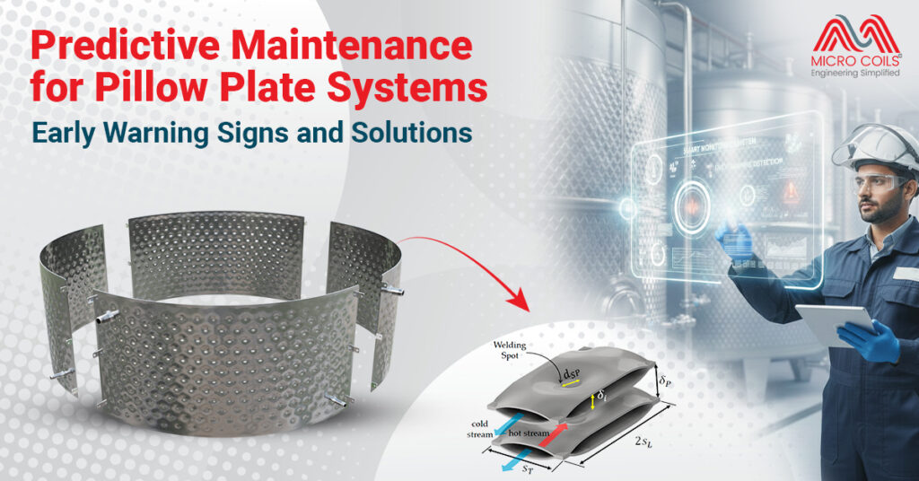
Stainless steel systems are more corrosion-resistant but can suffer from stress corrosion cracking in chloride environments – watch for hairline cracks near welds. Exotic materials like titanium or Hastelloy are highly resistant to chemical attack but may show different thermal expansion behaviors. Adjust your baseline parameters accordingly. The key is understanding your specific material’s vulnerabilities and focusing inspection efforts there. Document material specifications when purchasing from pillow plate manufacturers so your maintenance team knows exactly what they’re working with.
Yes, excessive humidity above 60% causes rapid condensation on your evaporator coil that can freeze and block airflow. High moisture also promotes mold growth on refrigeration coils, creating sticky buildup that traps dust and restricts air passage significantly.
Water overflow typically indicates a frozen evaporator coil that melts during off cycles, overwhelming the drain pan. Ice forms from restricted airflow, then melts rapidly when the system stops, producing more water than the pan handles properly.
Temporary improvement after shutdown indicates ice buildup on your AC evaporator coil during operation. The ice melts while off, restoring airflow briefly. This pattern points to underlying issues like low refrigerant or dirty refrigeration coils causing progressive freezing.
Evaporator Coil Airflow Problems: Diagnosis and Solutions Read More »