
What Is the Difference Between HVAC and AC? A Complete Guide
When people talk about keeping their homes comfortable, the terms HVAC and AC often get used as if they mean the same thing. They do not. Understanding the difference between the two can help you make smarter decisions about your home’s comfort system, whether you are buying a new unit, upgrading your current setup, or simply trying to understand what the technician is talking about. This guide breaks it all down in plain, simple language so you walk away with a clear picture.
What Does HVAC Actually Mean?
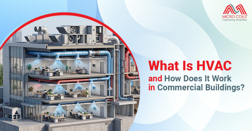
HVAC stands for Heating, Ventilation, and Air Conditioning. It is a complete system designed to manage the temperature, humidity, and air quality inside a building throughout the year. Think of it as an all-in-one comfort solution that handles both hot and cold seasons without needing separate systems for each. The term is widely used in residential, commercial, and industrial settings to describe the full range of climate control equipment working together.
The “H” in HVAC covers heating, which typically comes from a furnace, heat pump, or boiler. The “V” stands for ventilation, which is responsible for moving fresh air in and pushing stale air out, keeping indoor air healthy to breathe. The “AC” part handles cooling, and that is where the overlap with a standalone air conditioning unit begins. Together, these three components create a system that works year-round, adapting to whatever season you are in.
What Is AC?
AC, or air conditioning, refers specifically to the cooling function within a larger comfort system. It is not a complete home comfort solution on its own, but rather one piece of the bigger HVAC puzzle.
A standalone AC unit focuses entirely on removing heat and humidity from indoor air. It pulls warm air over a refrigerant-filled coil, cools it down, and then pushes that cooled air back into the room.
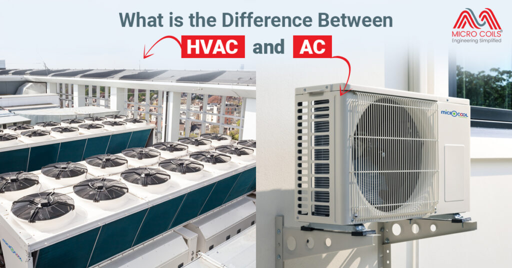
HVAC vs. AC: Understanding the Key Differences
Many people use the terms HVAC and AC interchangeably, but they are not the same. While both systems contribute to indoor comfort, HVAC offers a more comprehensive climate control solution compared to a standalone air conditioning system.
- HVAC is a Complete Climate Control System
An HVAC setup can cool indoor spaces during hot weather, provide heating during colder months, and maintain proper ventilation to improve indoor air quality. This all-in-one approach makes HVAC systems suitable for residential, commercial, and industrial environments where year-round comfort is essential. - AC Focuses Only on Cooling
An air conditioning (AC) system is designed primarily to lower indoor temperatures and remove excess humidity from the air. It works by extracting heat from the indoor environment and releasing it outdoors. While an AC unit can significantly improve comfort during summer, it does not provide heating or comprehensive ventilation capabilities. - Ventilation is a Major Differentiator
One of the most important advantages of HVAC systems is ventilation. HVAC units continuously circulate and filter air, helping remove dust, allergens, odors, and airborne contaminants. This feature contributes to healthier indoor environments. Traditional AC systems typically recirculate indoor air and offer limited air purification capabilities. - HVAC Systems Offer Greater Energy Management
Modern HVAC systems often include smart controls, zoning options, programmable thermostats, and energy-efficient technologies. These features allow users to regulate temperature more precisely while reducing energy consumption. In contrast, standard AC systems focus mainly on cooling performance and may provide fewer opportunities for integrated energy management. - Applications Vary Based on Requirements
AC systems are commonly used in homes, apartments, and small offices where cooling is the primary concern. HVAC systems, however, are preferred in large commercial buildings, hospitals, manufacturing facilities, hotels, educational institutions, and modern residential developments that require complete temperature control and superior air quality throughout the year. - Cost and Complexity Differences
Since HVAC systems combine heating, cooling, and ventilation functions, they are generally more complex and involve higher installation costs. However, they deliver broader functionality and long-term value. AC systems are usually less expensive to install initially, making them a practical option for spaces that only require cooling solutions.
How the Cooling Process Works in Both Systems?
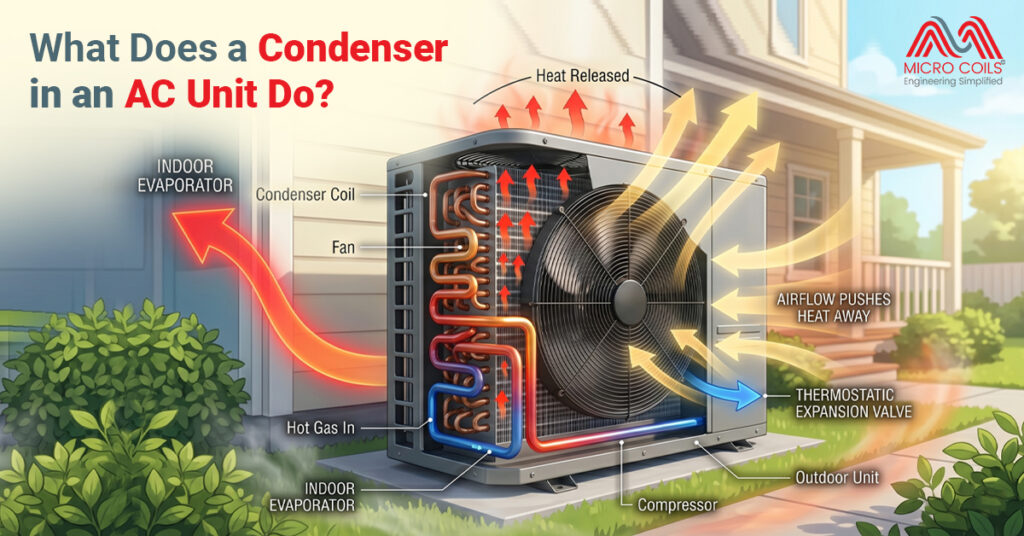
Both HVAC systems and standalone AC units use refrigeration cycles to cool the air inside a building. The process involves a refrigerant that absorbs heat from indoor air and releases it outside, leaving your space feeling cooler. This cycle runs through several components including a compressor, a condenser, an expansion valve, and a coil that handles heat absorption indoors. Whether you have a full HVAC setup or just a window AC unit, this basic refrigeration principle stays the same.
One of the most important components in this cooling process is the evaporator coil, which sits on the indoor side of the system and absorbs heat from the warm air passing over it. The refrigerant inside this coil evaporates as it absorbs heat, which is exactly how the space gets cooled. Without this coil working properly, neither an AC unit nor an HVAC system can cool effectively. Regular maintenance of this coil is essential to keeping your energy bills in check and your system running at full capacity.
Key Components: What Sets HVAC Apart from AC?
The biggest structural difference between HVAC and AC lies in the number of components involved. An AC unit typically needs only a few core parts to function. An HVAC system, by contrast, brings together several different units and components to handle heating, ventilation, and cooling all at once. Knowing what each system includes helps you understand why HVAC is generally more expensive to install but more versatile in the long run.
Here is a breakdown of the key components found in each system:
AC Unit Components:
- AC cooling coil (also called the evaporator coil): Absorbs heat from indoor air and enables the cooling cycle to work. It sits inside the air handler or directly in the unit and is one of the most maintenance-sensitive parts.
- Compressor: Pressurizes the refrigerant so it can cycle between liquid and gas states efficiently.
- Condenser coil: Located on the outdoor unit, this releases the heat absorbed from indoors into the outside air.
- Expansion valve: Controls the flow of refrigerant into the evaporator coil, regulating the cooling capacity.
- Air filter: Removes dust and debris from the air before it passes over the coil.
Additional Components Found in HVAC Systems:
- Furnace or heat pump: Provides heating during colder months, making the system useful year-round.
- Heat exchanger: Transfers heat from combustion gases to the air in gas furnace setups without mixing the two airstreams.
- Ductwork: A network of channels that distributes conditioned air throughout the entire building.
- Ventilation fans and fresh air intakes: Bring in outside air and push stale indoor air out, improving overall air quality.
- Thermostats and control systems: More advanced HVAC setups use programmable or smart thermostats to manage all functions from a single interface.
Heating Capability: The Big Differentiator
Heating is the single most defining difference between HVAC and AC. A standard AC unit simply cannot heat your home. When the temperature drops in winter, an AC-only setup leaves you completely dependent on a separate heating system like a space heater or a gas furnace. HVAC systems were built specifically to avoid this problem by integrating heating directly into the overall comfort solution.
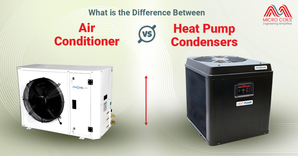
Most HVAC systems use either a gas furnace or a heat pump to provide warmth during cold months. Heat pumps are especially popular because they can both heat and cool a space by reversing the refrigerant cycle depending on the season. This dual-function capability makes an HVAC system far more economical over the course of a full year compared to running two separate systems. For anyone living in a region with both hot summers and cold winters, an HVAC system is almost always the more practical long-term choice.
Ventilation: The Often Overlooked “V” in HVAC
Most people think about temperature when they talk about comfort, but air quality matters just as much. The ventilation component of an HVAC system is responsible for replacing stale indoor air with fresh outdoor air on a regular cycle. Poor ventilation leads to a buildup of carbon dioxide, allergens, and other pollutants that can affect your health over time. This is a function that a standalone AC unit simply does not provide.
An AC unit circulates the air that is already inside the room. It cools it, filters some dust, and pushes it back out, but it does not bring in fresh air from outside. Over time, in tightly sealed modern homes, this can lead to stuffy, low-quality air that feels uncomfortable even at the right temperature. HVAC systems address this by designing ventilation into the overall airflow plan, ensuring that indoor air stays fresh and healthy regardless of the season.
Energy Efficiency: Which System Saves More?
Energy efficiency is a common concern for homeowners, and the comparison between HVAC and AC is worth thinking through carefully. A full HVAC system has more components, but it is designed to work as an integrated whole, which often makes it more efficient than running multiple separate systems. Modern HVAC units come with high ISEER ratings that reflect performance across both heating and cooling modes. This integrated efficiency is one of the main reasons HVAC systems have become the standard in most new construction.
A standalone AC unit can be very efficient at cooling, but it only addresses one season. If you are using an AC unit in summer and an electric space heater in winter, you are likely spending more on energy than you would with a well-matched HVAC setup. Proper installation, regular filter changes, and keeping the AC evaporator coil clean all play a major role in how efficiently any cooling system performs. The better maintained your system is, the less energy it uses to keep your space comfortable.
Installation: What to Expect for HVAC vs. AC?
Installing a standalone AC unit is generally simpler and less expensive than installing a full HVAC system. Window units or portable ACs can be set up with minimal professional involvement, making them appealing for renters or people who only need cooling in one room. Central AC systems require professional installation, ductwork, and proper sizing, but they are still less complex than a full HVAC setup that also includes heating and ventilation equipment. The upfront cost difference is significant, but so is the difference in what you get.
HVAC installation involves coordinating multiple systems, running ductwork through walls and ceilings, and ensuring that heating, cooling, and ventilation all work together smoothly. This process takes longer and costs more, but the result is a home comfort solution that works all year without requiring additional equipment. Most HVAC contractors will also test and balance the system after installation to make sure airflow is consistent across all rooms. For a permanent home, this level of investment typically pays off within a few years through energy savings and reduced maintenance costs.
Final Thoughts
HVAC and AC are not the same thing, even though one is contained within the other. AC handles cooling only. HVAC handles cooling, heating, and ventilation together, making it a much more complete system for whole-home comfort. Both rely on the same basic refrigeration principles to cool the air, but HVAC goes several steps further by managing your indoor environment across all seasons. Understanding this difference helps you ask better questions, compare the right options, and ultimately choose a system that fits your home, your climate, and your budget.
No. AC (Air Conditioning) is only responsible for cooling indoor spaces, while HVAC (Heating, Ventilation, and Air Conditioning) is a complete system that provides heating, cooling, and ventilation. In simple terms, every AC can be part of an HVAC system, but not every HVAC system is just an AC.
The better option depends on your needs. HVAC systems offer year-round comfort through heating, cooling, and air circulation. AC systems focus solely on cooling and are often more affordable. For comprehensive climate control, HVAC is generally the preferred choice.
Yes. Air conditioning is one of the core components of an HVAC system. HVAC combines cooling, heating, and ventilation into a single integrated solution, making it more versatile than a standalone AC unit.
HVAC systems involve additional components such as furnaces, heat pumps, ductwork, ventilation systems, and advanced controls. Since they perform multiple functions beyond cooling, installation and maintenance costs are typically higher than those of standard AC systems.
Modern HVAC systems can be highly energy efficient due to smart thermostats, zoning controls, and advanced technologies. While AC units can also be efficient, HVAC systems often provide better overall energy management when heating, cooling, and ventilation requirements are considered together.
Homes in regions with varying seasonal temperatures typically benefit from HVAC systems because they provide both heating and cooling. In consistently warm climates, a standalone AC system may be sufficient to maintain indoor comfort.
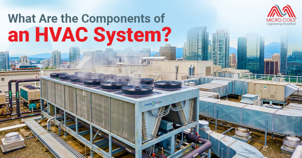
An HVAC system generally consists of heating equipment, cooling units, ventilation components, air filters, ductwork, and thermostatic controls. Together, these elements regulate temperature, airflow, humidity, and indoor air quality throughout a building.
What Is the Difference Between HVAC and AC? A Complete Guide Read More »