
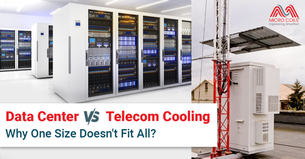
Data Center vs. Telecom Cooling: Why One Size Doesn’t Fit All
When it comes to keeping critical electronic equipment running smoothly, cooling isn’t just important—it’s essential. Both data centers and telecom facilities face the challenge of managing heat generated by power-hungry equipment. However, assuming that what works in a data center will automatically work for a telecom unit is a costly mistake that many infrastructure managers make.
The cooling requirements, environmental conditions, and operational constraints differ dramatically between these two types of facilities. Understanding these differences is crucial for selecting the right cooling solutions that ensure reliability, efficiency, and cost-effectiveness. Let’s explore why a one-size-fits-all approach simply doesn’t work in this critical aspect of infrastructure management.
The Fundamental Differences Between Data Center vs. Telecom Unit
At first glance, data centers and telecom facilities might seem similar. Both house electronic equipment that generates heat. Both require consistent temperature control to prevent failures. Both need reliable power supplies. However, that’s where the similarities end.
Data centers are typically large, centralized facilities. They’re often located in controlled environments with substantial infrastructure support. Most data centers have dedicated engineering teams on-site. They benefit from economies of scale, redundant systems, and sophisticated monitoring capabilities.
Telecom facilities tell a different story entirely. A telecom unit might be a small shelter at the base of a cell tower in a rural area. It could be a cabinet mounted on a rooftop in an urban environment. These installations are often unmanned, remotely monitored, and exposed to harsh environmental conditions. The equipment inside might range from a few hundred watts to several kilowatts of heat load.
This fundamental difference in scale, location, and accessibility drives completely different cooling requirements.
Environmental Challenges: Controlled vs. Uncontrolled
Data centers enjoy relatively controlled environments. They’re built with climate control in mind. Temperature and humidity are managed carefully. Clean power is available. Dust infiltration is minimized through air filtration systems.
Telecom installations face the opposite scenario. An outdoor telecom unit on a desert highway experiences extreme temperature swings—scorching days and cold nights. A coastal installation battles salt-laden air and high humidity. Mountain sites deal with snow, ice, and dramatic altitude-related challenges.
Consider a cell tower in rural India during monsoon season. The telecom unit must operate reliably despite 95% humidity, driving rain, and temperatures exceeding 40°C. Now imagine the same equipment in a Himalayan location where winter temperatures plunge below freezing and dust storms are common.
These environmental extremes demand cooling solutions designed specifically for harsh, variable conditions. What works perfectly in a temperature-controlled data center building would fail rapidly in such environments.
Access and Maintenance Considerations for Data Centers and Telecom Units
When a cooling system in a data center needs attention, trained technicians are typically on-site or nearby. Spare parts are readily available. Maintenance can happen quickly. This accessibility allows for more complex cooling systems with multiple components and controls.
Telecom sites present entirely different maintenance challenges. Many installations are in remote locations—mountain tops, desert areas, or offshore islands. Reaching these sites might require hours of travel. Some locations are accessible only by helicopter or require special permits.
A malfunctioning cooling system in a remote telecom unit can’t wait for next-day service. Equipment overheating means dropped calls, lost data connections, and unhappy customers. Yet sending technicians to remote sites for routine maintenance is prohibitively expensive.
This reality demands cooling solutions that are exceptionally reliable and require minimal maintenance. Simplicity becomes a virtue. Fewer moving parts mean fewer failure points. Systems that can self-diagnose and alert operators remotely become invaluable.
Power Availability and Constraints for Data Centers and Telecom Units
Data centers typically have abundant, reliable power available. Multiple utility feeds, backup generators, and UPS systems ensure continuous operation. Cooling systems can be sophisticated and power-hungry if needed.
Telecom installations often operate under severe power constraints. A tower site might rely on solar panels with battery backup. Grid power, when available, might be unreliable. Every watt consumed by cooling is a watt unavailable for the primary communications equipment.
This power scarcity fundamentally changes cooling system design. Energy efficiency isn’t just desirable—it’s absolutely critical. Adiabatic cooling systems, which use water evaporation to enhance cooling efficiency without mechanical refrigeration, become attractive for telecom unit applications in suitable climates.
Traditional air conditioning systems that work well in data centers might consume too much power for telecom applications. Alternative approaches like heat exchangers, free cooling, and hybrid systems often make more sense.
Heat Density and Distribution for Data Centers and Telecom Units
Modern data centers often deal with extremely high heat densities. Server racks can generate 15-20 kW or more per rack. Hot aisles and cold aisles are carefully managed. Cooling must be precise and powerful.
Telecom equipment typically generates lower heat densities but presents different challenges. A base station telecom unit might produce 2-5 kW total. However, this heat is often concentrated in a small, poorly ventilated space. The equipment layout might not allow for optimal airflow patterns.
Additionally, telecom equipment heat loads can vary significantly with network traffic. A cell site might run relatively cool during nighttime hours but heat up dramatically during peak usage periods. Cooling solutions must adapt to these fluctuating demands efficiently.
The cooling approach for a high-density data center rack—precision air conditioning with carefully controlled airflow—would be overkill and wasteful for most telecom applications. Instead, simpler yet robust solutions tailored to the specific heat load characteristics work better.
Space Constraints for Data Centers and Telecom Units
Data centers are designed with cooling infrastructure in mind. Raised floors accommodate under-floor cooling distribution. Ceiling space houses return air ducts. Mechanical rooms house chillers and air handling equipment. Space planning considers current and future cooling needs.
A telecom unit operates under severe space constraints. An outdoor cabinet might measure just 2 meters tall by 1 meter wide. Every cubic centimeter is precious. Rooftop installations have weight limitations. There’s no mechanical room, no raised floor, no luxury of space.
Cooling solutions for telecom must be compact and efficient with space utilization. Roof-mounted cooling units, through-wall heat exchangers, and integrated cooling systems become necessary. The cooling equipment must fit within or immediately adjacent to the communications equipment housing.
Climate Adaptability Requirements for Data Centers and Telecom Units
A data center cooling system operates in one location with relatively predictable conditions. You design for that specific environment and optimize accordingly.
Telecom networks span diverse climates. A mobile operator might have thousands of sites across a country. Some sites are in hot deserts. Others are in humid tropical regions. Still others face sub-zero winter temperatures.
This geographic diversity creates a dilemma. Do you design different cooling solutions for each climate zone? That approach increases complexity, spare parts inventory, and training requirements. Or do you find versatile solutions that work across multiple environments?
Many telecom operators prefer standardized solutions that can adapt to various climates. Adiabatic cooling systems with intelligent controls can operate efficiently in both dry and humid conditions. Heat exchangers with variable speed fans can adjust to ambient temperature variations. Hybrid systems that switch between cooling modes based on conditions offer flexibility.
Reliability vs. Efficiency Trade-offs for Data Centers and Telecom Units
Data center cooling emphasizes both reliability and efficiency, but when push comes to shove, efficiency often wins. Sophisticated systems with multiple stages, variable speed controls, and optimization algorithms maximize energy efficiency. If one component fails, redundant systems take over.
Telecom cooling must prioritize reliability above all else. A failed cooling system in a remote telecom unit means equipment shutdown and service outages. There’s no redundant system standing by. There’s no maintenance team on-site to quickly replace failed components.
This reliability imperative drives design choices. Simpler systems with fewer potential failure points are preferred. Passive cooling elements that have no moving parts are attractive. When mechanical systems are necessary, they must be exceptionally robust.
Adiabatic cooling systems, for example, can provide excellent efficiency in suitable climates. However, they require water supply and regular maintenance to prevent mineral buildup and biological growth. For remote telecom sites, this maintenance requirement might outweigh the efficiency benefits. A simpler air-to-air heat exchanger, while less efficient, might be the better choice for long-term reliability.
Cost Structures and Economics for Data Centers and Telecom Units
Data center cooling represents a significant capital investment, but operational efficiency quickly becomes the dominant cost factor. With continuous operation and high power consumption, even small efficiency improvements generate substantial savings. Sophisticated, expensive cooling systems with payback periods of 3-5 years make economic sense.
The economics of telecom unit cooling are different. Individual sites have relatively low cooling loads. Capital costs must be minimized because they’re multiplied across hundreds or thousands of installations. Simple, robust cooling solutions with lower upfront costs often win despite somewhat lower efficiency.
Maintenance costs weigh heavily in telecom economics. A system requiring quarterly filter changes might seem reasonable for a data center. For a telecom site requiring expensive truck rolls to remote locations, those same maintenance requirements become cost-prohibitive.
Total cost of ownership calculations must include not just energy consumption but also maintenance frequency, spare parts availability, system lifespan, and replacement logistics. Often, a slightly less efficient but far more reliable and maintenance-free solution proves more economical over the equipment lifetime..
Noise and Aesthetic Considerations
Data centers are industrial facilities where noise is manageable through proper engineering. Cooling equipment can be loud if necessary. Aesthetics are rarely a concern—function trumps form.
Telecom installations often face strict noise regulations, especially in residential areas. A rooftop telecom unit in an urban neighborhood can’t generate excessive noise that disturbs residents. Cooling fans, compressors, and airflow must be acoustically managed.
Aesthetic concerns also arise. Visible telecom equipment already faces community resistance. Large, industrial-looking cooling equipment can exacerbate these concerns. Compact, discreet cooling solutions that blend with surroundings become important for site approval and community relations.
The Right Approach for Each Application
So what does all this mean for infrastructure managers? Simply put: stop assuming that data center cooling best practices apply to telecom installations. They don’t.
- For data centers, continue pursuing high-efficiency, sophisticated cooling systems. Invest in optimization. Leverage economies of scale. Use precision cooling where needed. The controlled environment and operational support justify these approaches.
- For telecom unit installations, take a different path. Prioritize reliability and simplicity. Choose cooling solutions that can withstand harsh environments with minimal maintenance. Consider adiabatic cooling where climate and water availability suit it, but don’t force it where simpler solutions work better.
- Evaluate each site’s specific conditions. Desert locations might benefit from evaporative cooling approaches. Coastal sites need corrosion-resistant materials. Cold climate installations might use free cooling extensively. Urban rooftop sites require noise management.
- Standardize where possible, but recognize that some climate zones might require different solutions. A telecom operator spanning tropical and arctic regions probably needs at least two different cooling approaches in their portfolio.
Conclusion
The cooling needs of data centers and telecom facilities differ fundamentally in almost every aspect. Environment, accessibility, power availability, space constraints, and operational requirements create distinctly different challenges demanding distinctly different solutions.
Data center cooling can be sophisticated, centrally managed, and highly optimized. Telecom unit cooling must be robust, simple, and able to operate autonomously in harsh conditions with minimal maintenance.
Success requires understanding these differences and selecting cooling solutions appropriate for each application. Don’t force data center solutions into telecom applications or vice versa. Recognize that what works brilliantly in one context might fail miserably in another.
Whether you’re deploying adiabatic cooling, heat exchangers, or air conditioning systems, match the technology to the specific requirements and constraints of your application. One size truly doesn’t fit all in the world of critical infrastructure cooling. The sooner operators recognize this reality, the more reliable and cost-effective their cooling systems will become.
While some manufacturers offer products for both applications, using identical equipment is rarely optimal. Data center-grade cooling units often have features you’re paying for but won’t use in telecom applications—sophisticated controls, multiple redundancy options, and integration capabilities. Conversely, they may lack ruggedization needed for outdoor telecom unit deployments. Instead, choose equipment specifically designed for each environment. Look for telecom-rated equipment with IP ratings for weather resistance, extended temperature ranges, and simplified maintenance. This targeted approach reduces upfront costs for telecom sites while ensuring reliability where it matters most.
Keep calibration records to identify sensors that drift frequently – these might need replacement rather than repeated calibration. Some modern smart sensors include self-diagnostic features that alert you when calibration is due. Always calibrate after any system upset, collision, or suspected sensor damage. Consider keeping a calibrated spare sensor on hand for critical measurement points so you can swap and verify readings if you suspect accuracy issues.
Adiabatic cooling works in humid climates but with reduced effectiveness compared to dry environments. In high humidity, evaporative cooling potential decreases since the air is already moisture-saturated. However, modern hybrid adiabatic cooling systems can still provide benefits by pre-cooling ambient air before it enters heat exchangers, improving overall efficiency even in humid conditions. The key consideration for telecom applications is water availability and quality. Humid regions often have better water access, but you’ll need proper water treatment to prevent biological growth and mineral scaling. Evaluate total cost of ownership including water consumption, treatment, and maintenance against simpler air-cooled alternatives for your specific climate.
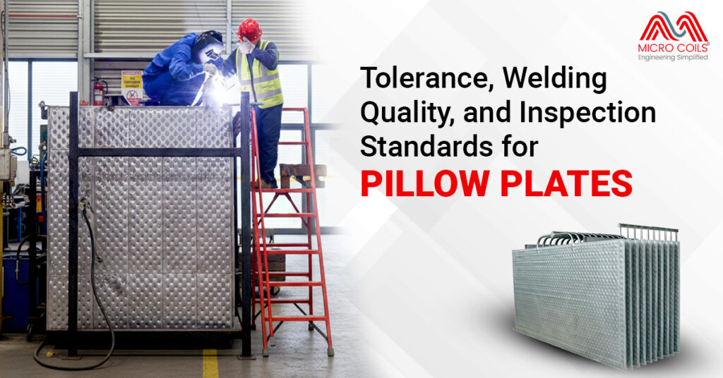
Stainless steel systems are more corrosion-resistant but can suffer from stress corrosion cracking in chloride environments – watch for hairline cracks near welds. Exotic materials like titanium or Hastelloy are highly resistant to chemical attack but may show different thermal expansion behaviors. Adjust your baseline parameters accordingly. The key is understanding your specific material’s vulnerabilities and focusing inspection efforts there. Document material specifications when purchasing from pillow plate manufacturers so your maintenance team knows exactly what they’re working with.
Free cooling becomes effective when outdoor temperature is at least 5-8°C below your telecom unit target temperature, though exact thresholds depend on equipment heat load and cabinet design. Most telecom equipment safely operates up to 35-40°C, so free cooling works when ambient temperatures fall below 27-32°C. However, you must consider humidity and air quality—bringing in outdoor air also introduces moisture and contaminants. Many telecom cooling solutions use indirect free cooling via heat exchangers, which separates outdoor and indoor air streams. This approach allows temperature benefits without humidity and contamination issues. Calculate annual hours when your location’s climate permits free cooling to determine potential energy savings.
Continuous operations show steadier trends, making anomaly detection simpler. A gradual pressure increase over weeks clearly indicates fouling. With batch systems, compare cycle-to-cycle performance instead. If heating time gradually increases from 45 minutes to 65 minutes over multiple batches, that’s your warning sign. Use statistical process control methods to track batch-to-batch variations. Many dry cooler applications run continuously, making trend analysis more straightforward than batch reactor applications.
Simple observation provides valuable clues. If cooling units cycle on and off frequently (short-cycling), you’re likely oversized—the system cools too quickly then shuts down, wasting energy and stressing components. If equipment runs continuously at maximum capacity even during moderate weather, you’re undersized. Check internal telecom unit temperatures with an inexpensive handheld thermometer during peak heat periods—readings consistently above 30°C suggest inadequate cooling. Monitor utility bills; unexpectedly high energy consumption relative to similar sites indicates inefficiency from improper sizing. For basic verification, calculate actual heat load from equipment nameplates and compare against cooling system capacity. A properly sized system runs at 60-80% capacity during peak conditions, providing headroom without excessive waste.
However, certain conditions demand immediate action: sudden pressure drops suggesting catastrophic leaks, rapid temperature spikes indicating loss of cooling, unusual smells suggesting chemical reactions or overheating, or visible deformation of the plates themselves. Create a severity matrix with your operations team defining green (monitor closely), yellow (schedule maintenance soon), and red (shut down now) conditions.
Unlike data centers where N+1 redundancy is standard, most telecom unit installations use single cooling systems without backup. The economics and practicalities don’t support redundancy for individual cell sites. Instead, reliability comes from robust, proven equipment designed for continuous operation. However, critical hub sites or locations serving large populations might justify redundant cooling solutions. A practical middle ground is designing systems to fail-safe—if cooling fails, equipment can operate in reduced capacity mode or emergency ventilation prevents catastrophic overheating until repairs arrive. Some operators keep spare cooling units in regional warehouses for quick deployment rather than installing redundant systems at every site. Balance redundancy costs against service level requirements and site criticality.
Conversely, if pressure gauges before and after the pillow plates show normal differential but your pump is running hot or drawing excessive current, the pump is struggling. Use a methodical approach: check simple things first like valve positions and strainer condition before assuming pillow plate problems. Temperature profiling helps tremendously – if inlet and outlet temperatures are correct but surface temperatures are wrong, internal pillow plate issues are likely.
Data Center vs. Telecom Cooling: Why One Size Doesn’t Fit All Read More »